Here i am going to explain you a simple Password based circuit Breaker Project using PIC Microcontroller. This project is much similar to my previous one, “Password Based Door Locking System”.

Circuit breakers are electromechanical devices used in the power system to connect or disconnect the power flow at the generator, substation, or load location. Only authorised persons with correct password can connect or disconnect the circuit breaker. Each Line will have separate passwords to operate, By entering the password the current state of the line is toggled. That is, the load will gets connected or disconnected. For verification, after entering the password you need to press the ‘=’ button on keypad (Which is just like an ‘ENTER’ key).
Block Diagram of the Password based Circuit Breaker
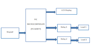
PIC16F877 is the heart of this project, which takes input from keypad as password and displays the current status on a 16×2 LCD Display. For the demonstration purpose, I am using only two loads, which is controlled by two relays.
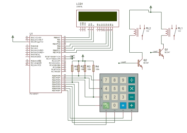
“1234” and “9876” are the two passwords used here for activating and deactivating the Load 1 and Load 2 respectively. As I mentioned in the above paragraph, don’t forget to enter ‘=’ after feeding the password. Press ‘ON/C’ Button to clear the screen.
Circuit Diagram of Password Circuit Breaker
 Embedded C Code
The post Password Based Circuit Breaker using PIC Microcontroller with C code appeared first on PIC Microcontroller.