Quantcast
Channel: circuit | Battery Guide
Viewing all 239 articles
Browse latest View live

Passive Infrared Detector Circuit

$
0
0

The infrared (IR) is invisible radiant energy, electromagnetic radiation that we cannot see with our eyes, but we can sometimes feel on our skin as heat. The infrared light falls just outside the visible spectrum, beyond the edge of what we can see as red. Most of the thermal radiation emitted by objects near room temperature is infrared.

Passive Infrared Detector Circuit

The circuit uses a MCP6032 microchip operational amplifier. The MCP6032 operational amplifier (op amp) has a gain bandwidth of 10kHz with a low typical operating current of 900nA and an offset voltage that is less than 150uV. The MCP6032 uses Microchip’s advanced CMOS technology, which provides low bias current, high-speed operation, high open-loop gain and rail-to-rail input and output swing. The MCP6032 operates with a single supply voltage that can be as low as 1.8V, while drawing less than 1uA of quiescent current. The MCP6032 is available in standard 8-lead SOIC and MSOP packages. It also includes, a PID20 integrated circuit and a few electronic components. The size of the output signal of PID20 is determined by the task at pins 3 and 4. The output signal at pin 3 is compared with a reference voltage equal to half the supply voltage. The reference voltage is taken from the voltage divider R2-R3-R4-R5. When approaching an object warmer than the surrounding environment, or to remove an object colder than the environment, the output voltage increases. The variation of the sensor output will be compared, the IC2a and IC2b, located voltage of 0.5V under and over voltage reference respectively. Depending on the output, one of the comparators calculates and activates T1.

This basic circuit is used in night-vision devices with infrared illumination, which allows people or animals to be observed without the observer being detected. The infrared light is also used in industrial, scientific, and medical applications as well as in consumer devices.

For more detail:  Passive Infrared Detector Circuit


The post Passive Infrared Detector Circuit appeared first on PIC Microcontroller.


Password Based Circuit Breaker

$
0
0

Electrical accidents are rapidly increasing especially electric line repairs incident due to the lack of communication and coordination between the maintenance personnel and the electric substation staff. The password based circuit breaker device could just be the solution as only the lineman could reliably control the circuit breaker to avoid miscommunication. The system requires a password to turn ON/OFF the circuit breaker as needed. It is entirely controlled by 8051 family microcontroller specifically the SST89E54RDA-40-C-PIE, an 8-bit microcontroller that is a member of the Flash Flex family.

Password Based Circuit Breaker

The circuit consists of 8051 series controller, 4×3 keypad, LCD, relays and two loads. LCD data pins are connected to port1 and control pins RS, RW, EN pins are connected to P3.7, P3.6 and P3.5 respectively. The keypad is connected to port 2 of the controller while the LCD is used to display the information. In addition, the lamp and motor are connected to P3.0 and P3.1 through the relays. These are used to indicate circuit breaker state. Moreover, BC547 transistors are used to drive the relays where 5V relays are used to drive the AC loads. While giving the connections, there should be no common connection between AC and DC supplies. Furthermore, a 5V power supply is used to provide regulated 5V DC to the controller.

This project distinctly provides security and convenience to electrical maintenance personnel. This may help avoid fatal accidents to line man, which can be used in establishments such as building offices, hotels, industries and houses. It is a simple project with commonly available components that helps save life.

For more detail:  Password Based Circuit Breaker


The post Password Based Circuit Breaker appeared first on PIC Microcontroller.

Q-matic Circuit Application of PIC16F877 Microcontroller

$
0
0

In this article I used in banks and hospitals will give information about the Q-matic s. I’ve done a routing circuit board (main board) and consists of three separate teller. Routing PIC16F877 on board, if the teller did not use pic16f876 in each. Teller as the officer may increase, decrease or can be reset. Every teller has been working with the same logic.Q-matic Circuit Application of PIC16F877 Microcontroller

Their value as a teller at regular intervals each orientation is sent to the board. Clipboard routing information from each teller overlook the ordinary. Each of the received data and also shows teller number of their displace. Each display is working with the logic scan.

PIC16F877 Q-matic Circuit Schematic

Each displace the software are as follows; a first rank value, tens and hundreds digit is determined. This value is shown in the display of the first one’s place and then later on they face, including the step sequence is shown, and this is very fast, is difficult to detect with the human eye. We’ll just see on the screen the entire sequence value. This scanning period will normally need to be 14ms. But I’ve adjusted according to the simulation program.Q-matic Circuit Application of PIC16F877 Microcontroller schematich

Q-matic Circuit Test

Author Ediz Ağarer – Micro-controller controlled the Q-matic application circuit schematic source code files: q-matic-circuit-application-of-pic16f877-microcontroller.ZIP


For more detail: Q-matic Circuit Application of PIC16F877 Microcontroller

The post Q-matic Circuit Application of PIC16F877 Microcontroller appeared first on PIC Microcontroller.

PIC12F675 Microcontroller Based Security Alarm Circuit

$
0
0

Crime in general is still on the rise, and having a security alarm installed is no longer a perquisite of the wealthy! Here is a simple and compact security alarm system to protect your home/shop and valuables. The circuit is built around a tiny microcontroller chip PIC12F675. Besides, a ready-made Passive Infrared (PIR) module is integrated with the alarm system for reliable human-motion detection.
The built-in passive infrared sensor detects human movement by sensing temperature changes over the scene, and works even in the total darkness.PIC12F675 Microcontroller Based Security Alarm Circuit Human body heat moving across the scene will trigger the PIR sensor, and the trigger signal will be sent to the control circuit instantly. As the output of the alarm system can be connected to external lamps or alarm sirens, these devices will be instantly activated upon the detected motion. As a result, the intruder who entered the guarded area, even in total darkness, will instantly be exposed.

Note that PIR sensor can be used not only for detecting motion in the darkness, but it can even be used effectively in daytime where it may produce much less false alarms compared to other motion detection mechanisms. Here, the PIC12F675 works as a “logic interface” between the detection device and the alarm actuator.

Security Alarm Circuit Description

As stated, this project describes a home security alarm based on a Passive Infra-Red sensor module (PIR1). There are many vendors that manufacture the PIR sensor modules and almost all of them are pretty much the same in function. They have a single output that goes high (3.3V) when the motion is detected. Hera, a PIC12F675 (IC1) microcontroller continuously monitors the output from the PIR sensor module and turns an electro-magnetic relay (RL1) on when it goes active.

The circuit can be powered from four AA/AAA cells that gives 6 VDC supply. A 1N4007 (D1) diode is used in series to drop the voltage down to near 5.3 V as the operating voltage for the PIC microcontroller should be below 5.5 V. As well, this diode provides the protection to the whole electronics in case of reverse polarity of the power supply. PIR sensor modules usually have a 3-pin connection (Vcc, Output, and round). The pinout may vary, so it is recommend to check the manufacturer’s datasheet to confirm the pins. Sometime, they do have labels on the PCB next to the pins. Most PIR sensor modules can be powered through 5 to 12 VDC supply as it has its own “low-drop voltage regulator” chip, on board.

The output of the PIR sensor module (PIR1) is monitored through GP5 (pin 2) of PIC12F675. PIC12F675 is an 8-Pin Flash-Based 8-Bit CMOS Microcontroller. Note that,here the PIC12F675 microcontroller uses the internal clock oscillator at 4.0 MHz. When the motion is sensed, this output is high at about 3.3 V . You could still use this voltage as a valid logic high for IC1 by changing the code , but It is preferred to use this voltage to drive the base of a BC547 transistor (T1) so that at the collector we will have the full swing of the logic voltages.

When power supply is turned on by the on/off switch (S1), IC1 monitors the voltage at the collector of the transistor after a delay of about 60 seconds. This initial delay is introduced deliberately to avoid false triggerings, because the PIR sensor requires an initial stabilization time of about 10 to 60 seconds in order to function properly. A red LED (LED1) is connected to port GP0 of IC1 (pin7) with a current limiting resistor (R3) in series. The LED blinks at a slow rate during this delay time.PIC12F675 Microcontroller Based Security Alarm Circuit schematich

After this delay, IC1 starts monitoring the voltage at the collector of T1. The LED blinking pattern is now changed to indicate the “standby” mode. In standby mode, T1 is cut off, and the collector output is at logic high (+5 V). When a “valid” motion is sensed, the high output from the PIR sensor module saturates the transistor and the voltage at the collector drops down to logic low. Consequently, of port GP1 (pin 6) of IC1 goes high to switch on the 5V DPDT relay (RL1) through transistor T2. This output will remain High, as long as the motion exists, and this active condition is indicated by a steady-glow of LED1. DPDT Switching contacts of RL1 can be connected to powerful external lamps and/or alarms.


For more detail: PIC12F675 Microcontroller Based Security Alarm Circuit

The post PIC12F675 Microcontroller Based Security Alarm Circuit appeared first on PIC Microcontroller.

Microchip PIC Programmer ICSP Circuit Requirements

$
0
0

Microchip do not recommend any particular circuit for ICSP programming. There are diagrams for different tools, such as Pro Mate and PICKit2 with similar circuitry but slight variations. In some schematics, their suggested resistor values are too small, in our opinion, and can cause problems with programmers, even Microchip ones.

Microchip PIC Programmer ICSP Circuit

Kanda have developed a recommended In System Programming circuit that will work effectively with our PIC programmer range, and other PIC programmers. This circuit is shown in the diagram below. Please read the notes that describe the circuit and explain the effect of extra components such as capacitors. Microchip PIC Programmer ICSP Circuit Requirements

Notes on PIC ICSP Circuit
  1. Kanda programmers are designed to provide 3.3V or 5V to the target circuit, but some other ICSP programmers always supply 5V. If your circuit operates at a lower voltage than the programmer, then the diode shown on VDD should be fitted to protect the rest of the circuit. A series resistor may be acceptable instead of the diode in some cases.
    The maximum current that the programmer can supply is often limited, so you should fit the diode on VDD if the programmer over-current circuit trips.
  2. MCLR/VPP pin needs a resistor to VDD. A minimum of 1K should work but 10K is better. PIC16F devices with only VDD first ICSP entry (PIC16F8x/87x/7x/7×7) should be fitted with a 4K7 resistor as a minimum to reduce the possibility of code running before VPP rises. Supervisory circuits or push buttons on MCLR should be isolated from the VPP voltage, by placing them on the VDD side of the resistor or by fitting a Schottky diode on this line as per note 1.
  3. The 100nF capacitor shown on MCLR/VPP pin is optional for HVP but we do recommend that a capacitor is fitted to avoid glitches on MCLR. 100nF is the maximum value, and we recommend something smaller. Larger capacitors may prevent the PIC from entering HVP mode. Do not fit for LVP mode.
  4. If possible, Clock and Data lines should be dedicated to ICSP but where this is not possible, the application circuit should be isolated from the data and clock lines with series resistors, above 10K. This is especially important if either of these lines forces the pin as an input or output. In exceptional cases, series resistors may not be sufficient and a 4053 multiplexer or similar circuit should be used.
    Capacitors on these programming lines should be avoided if at all possible. If they are needed, for noise immunity for example, then the maximum capacitance that all programmers can handle is 1nF, although some are better.
  5. If LVP mode is used, this resistor must be fitted.
  6. The PGM line is only needed for Low Voltage Programming – LVP mode.
  7. PIC18F J parts need a decoupling capacitor between VccCore pin and Ground, typically 100nF.
Notes on PIC ICSP Circuit
  1. Kanda programmers are designed to provide 3.3V or 5V to the target circuit, but some other ICSP programmers always supply 5V. If your circuit operates at a lower voltage than the programmer, then the diode shown on VDD should be fitted to protect the rest of the circuit. A series resistor may be acceptable instead of the diode in some cases.
    The maximum current that the programmer can supply is often limited, so you should fit the diode on VDD if the programmer over-current circuit trips.
  2. MCLR/VPP pin needs a resistor to VDD. A minimum of 1K should work but 10K is better. PIC16F devices with only VDD first ICSP entry (PIC16F8x/87x/7x/7×7) should be fitted with a 4K7 resistor as a minimum to reduce the possibility of code running before VPP rises. Supervisory circuits or push buttons on MCLR should be isolated from the VPP voltage, by placing them on the VDD side of the resistor or by fitting a Schottky diode on this line as per note 1.
  3. The 100nF capacitor shown on MCLR/VPP pin is optional for HVP but we do recommend that a capacitor is fitted to avoid glitches on MCLR. 100nF is the maximum value, and we recommend something smaller. Larger capacitors may prevent the PIC from entering HVP mode. Do not fit for LVP mode.
  4. If possible, Clock and Data lines should be dedicated to ICSP but where this is not possible, the application circuit should be isolated from the data and clock lines with series resistors, above 10K. This is especially important if either of these lines forces the pin as an input or output. In exceptional cases, series resistors may not be sufficient and a 4053 multiplexer or similar circuit should be used.
    Capacitors on these programming lines should be avoided if at all possible. If they are needed, for noise immunity for example, then the maximum capacitance that all programmers can handle is 1nF, although some are better.
  5. If LVP mode is used, this resistor must be fitted.
  6. The PGM line is only needed for Low Voltage Programming – LVP mode.
  7. PIC18F J parts need a decoupling capacitor between VccCore pin and Ground, typically 100nF.Microchip PIC Programmer ICSP Circuit Requirements schematich

Kanda ICSP PIC Programmers

Kanda ICSP PIC ProgrammersKanda Handheld PIC Programmers will provide 3.3V or 5V VDD to target PIC microcontroller circuits. The target circuit can be powered or unpowered. This can be user selected for most PIC microcontrollers but it is fixed to 3.3V for J type PIC microcontrollers and LF parts that can be damaged by 5V. The high Voltage programming voltage (VPP) is set to 12V for most PIC devices but is automatically set to 9V for PIC18F K type and newest PIC16F PIC microcontrollers


For more detail: Microchip PIC Programmer ICSP Circuit Requirements

The post Microchip PIC Programmer ICSP Circuit Requirements appeared first on PIC Microcontroller.

Understanding silicon circuits: inside the ubiquitous 741 op amp

$
0
0

Why op amps are important

Op amps are a key component in analog circuits. An op amp takes two input voltages, subtracts them, multiplies the difference by a huge value (100,000 or more), and outputs the result as a voltage. If you’ve studied analog circuits, op amps will be familiar to you, but otherwise this may seem like a bizarre and pointless device. How often do you need to subtract two voltages? And why amplify by such a huge factor: will a 1 volt input result in lightning shooting from the op amp? The answer is feedback: by using a feedback signal, the output becomes a sensible value and the high amplification makes the circuit performance stable.

Understanding silicon circuits inside the ubiquitous 741 op amp

Op amps are used as amplifiers, filters, integrators, differentiators, and many other circuits.[2] Op amps are all around you: your computer’s power supply uses op amps for regulation. Your cell phone uses op amps for filtering and amplifying audio signals, camera signals, and the broadcast cell signal.

The structure of the integrated circuit

NPN transistors inside the IC

Transistors are the key components in a chip. If you’ve studied electronics, you’ve probably seen a diagram of a NPN transistor like the one below, showing the collector (C), base (B), and emitter (E) of the transistor, The transistor is illustrated as a sandwich of P silicon in between two symmetric layers of N silicon; the N-P-N layers make a NPN transistor. It turns out that transistors on a chip look nothing like this, and the base often isn’t even in the middle!


Symbol and oversimplified structure of an NPN transistor.

The photo below shows one of the transistors in the 741 as it appears on the chip. The different brown and purple colors are regions of silicon that has been doped differently, forming N and P regions. The whitish-yellow areas are the metal layer of the chip on top of the silicon – these form the wires connecting to the collector, emitter, and base.

Underneath the photo is a cross-section drawing showing approximately how the transistor is constructed. There’s a lot more than just the N-P-N sandwich you see in books, but if you look carefully at the vertical cross section below the ‘E’, you can find the N-P-N that forms the transistor. The emitter (E) wire is connected to N+ silicon. Below that is a P layer connected to the base contact (B). And below that is a N+ layer connected (indirectly) to the collector (C).[3] The transistor is surrounded by a P+ ring that isolates it from neighboring components.

For more detail:  Understanding silicon circuits: inside the ubiquitous 741 op amp

The post Understanding silicon circuits: inside the ubiquitous 741 op amp appeared first on PIC Microcontroller.

PIC16F84 Multiple Programming Circuit

$
0
0

So far I have not seen such a circuit in a web environment could work in mass production programming section has been removed by the original photos used only copying part of an integrated control pic16c64 asm lib, etc. scr. There are resource files (.lzh extension, you can open files with WinRAR) with one source can be copied pic 8 18 volt dc supply voltage is regulated with 78xx series

PIC16F84 Multiple Programming Circuit

Example of a project that will be different from the pic asm source code and hardware can be copied guess changing

The two AC power adapter from the regulator output from +5 V and +12 ~ 14V terminals are available. Thus, AC power adapter is needed about + 16V (using the AC adapter is rated at +12 V is used, try to measure the actual output was more than +16 V out). The capacity is about 500mA. No batteries are used in the experiment, we can note that the capacity problem.

This will be the master one PIC16C84 (or F84) will be targeted to a maximum total of eight programs PIC16C84 (or F84) was used to control the circuit diagram and writer writer had to copy those programs PIC16C64 . (Photo above is what you manufacture printed circuit boards produced by Mr) In addition to copy a simple comparison of the master and the target (compared to when we copy), and also give protection to the target after the copy of the program. PC The device is no need to connect with PC, operating independently, it is no use to anyone.PIC16F84 Multiple Programming Circuit schematich

Red and green LED is not a one has three legs. 3 Single red, single green, red to green and the simultaneous emission red, green and orange colors .

PIC16F84 Multiple Programming Circuit schematic pic assemby source code files : pic16f84-multiple-programming-circuit.rar


For more detail: PIC16F84 Multiple Programming Circuit

The post PIC16F84 Multiple Programming Circuit appeared first on PIC Microcontroller.

A pic programmer circuit based on AN589. using pic microcontoller

$
0
0

AN589 is microchip’s application note for a parallel port pic programmer circuit which I chose as I wanted something reliable to get up and running quickly.
It is really quite a simple circuit and its main objective is to provide ICSP connections to your pic microcontroller.

That the PGM signal is not provided – it’s not really necessary anyway as you can turn off PGM mode by programming the chip.  For first use of a chip you will need to pull the PGM line low as PGM is enabled by the manufacturer.

A pic programmer circuit based on AN589.

PIC Programmer Circuit diagram

Disclaimer : If you build this circuit you must double check each connection to the parallel port cable to avoid damage to your computer. This includes checking for shorts between each pin at the parallel port on your circuit. For initial testing it is best if you use a spare (old computer). Building this project is your own responsibility and I can not be held responsible for any damage to your computer.

Modifications

It has a few modifications that are useful and easy to do:
  • Transmission line termination – lets it work over a long cable.
  • LM317 voltage regulator to get 11.6 volts and protect the circuit
  • Power supply steering diode (stops you reverse connecting the supply).
  • Changed LM340-5 to 3pin 100mA LM78L05.
  • ICSP connector.
  • An LED to show that power is applied.
  • Changed 74LS244 to 74HCT244 because I had one handy!
  • Standard 10k resistors instead of 2k – just easier if they are all the same.

A pic programmer circuit based on AN589.

Circuit notes

Transmission line termination

The transmission line termination lets you use the pic programmer circuit at the end of a long cable – I am using a normal parallel cable ~6 feet long. If you want to know more about transmission line terminations then follow this link.

When I first tried to use it I got all kinds of random results so it is worth adding the termination.


For more detail: A pic programmer circuit based on AN589.

The post A pic programmer circuit based on AN589. using pic microcontoller appeared first on PIC Microcontroller.


PIC16C54 dual dice electronic project circuit

$
0
0

An electronic dice project circuit can be designed in various modes , using logic circuit or using microcontrollers . This electronic project is based on the PIC16C54 microcontroller , manufactured by Microchip . This project is a simple dual dice electronic project , that use few external electronic parts and LED displays , to generate ( simulate ) dices .PIC16C54 dual dice electronic project circuit

As you can see in the schematic circuit , the main advantage of this electronic dice project is that this circuit require few external electronic parts ( like many of the microcontroller based projects ) .

The circuit needs to be powered from a 5 volts DC power supply circuit , but you can use a 9 volts battery and a 5 volt three terminal regulator ( connected like in this circuit diagram ) .
 There are two I/O ports in the 16C54; one 8 bit & the other 4 bit. The 8 bit port, Port B, is connected to the 7 segment display. Three pins of the 4 bit Port A are used and the other pin is tied high. Pin 4 of the PIC is also tied high to give a power-on reset.

A 150R resistor acts as a current limiting resistor for each display. PIC ports have a maximum sourcing current of 40mA ( the maximum current for the LED display is 200mA so it is the PIC that R1 is protecting, not the display.)PIC16C54 dual dice electronic project circuit schematic

The PIC uses its internal RC clock oscillator option (with the 10K resistor, R3, and the 330pF capacitor, C2) and runs at about 330kHz. The switch is connected to input RA0. Normally this line is pulled high via R4 to +5V, but when the switch is closed the input is pulled low. The software detects the falling edge as a dice roll.
You can download souce code for this electronic project following this link

The post PIC16C54 dual dice electronic project circuit appeared first on PIC Microcontroller.

Infrared (IR) Object Detection Module Circuit Using IR LED and Photodiode

$
0
0

How to make Infrared (IR) sensor Object Detection Module Circuit Using IR LED and Photodiode

The IR Object Detection sensor module is quiet easy to make. This sensor circuit below is a low cost – low range infrared object detection module that you can easily make at home using IR LED’s.

We will use a photodiode and IR LED to make a simple circuit. IR led looks like a regular LED that you usually see in Television Remote controls.For now I have added a regular LED to glow as in indicator when something is detected, you can replace it with a buzzer or something else the way you wish.Infrared  Object Detection Module Circuit Using IR LED and Photodiode

The Main concept is simple, the IR led keeps transmitting IR infrared rays up to some range (there is a potentiometer also in the design with the help of which you can alter the range). When some object comes in the (IR) infrared range, the IR waves hits the object and comes back at some angle, The Photo diode next to IR led detects that IR infrared rays which got reflected from the object and hence works as a proximity sensor. You can read more details about Proximity sensors for more.

The components required to make this IR sensor can be easily found in any electronic stores and it is quiet inexpensive.

IR Sensor Circuit Module Requirements

1 – IR LED TSFF5210
1 – PR (photodiode) BPV10NF
1 – 1k resistance
1 – 220E resistance
1 – 6k8 resistance
1 – 10k potentiometer
1 – IC LM358

Infrared sensor Module Schematics

Following this schematic you can easily make it on a breadboard, I intentionally drew this schematic for this IR sensor this way so that it can easily printed on the copper board in no time if you have some etching solution.Infrared  Object Detection Module Circuit Using IR LED and Photodiode schematic

For now in this circuit an LED would glow as an example. Notice that there are three pins in the schematic in which two pins are used to provide power to the infrared sensor and the Middle pin is unused, and can be used for other operation. The Middle pin goes high (Logic 1) if the photodiode in this object detection module detects an object, and hence can be interfaced with other devices. You can use it the way you wish, it can be used to run some DC motors and make a simple robot. The middle pin of the IR Sensor Circuit can be interfaced with Microcontroller easily to do complex operations,or you can interface an LCD with microcontroller and have the status of the sensor displayed on the LCD very easily as in my next tutorial for interfacing multiple IR Sensors with Arduino and LCD.

For more detail: Infrared (IR) Object Detection Module Circuit Using IR LED and Photodiode

The post Infrared (IR) Object Detection Module Circuit Using IR LED and Photodiode appeared first on PIC Microcontroller.

lc meter capacimeter inductimeter circuit pic 16f84 auto range lcmeter

$
0
0

The good and high precision capacitor meter (Capacimeter) inductor meter (inductimeter) auto range lc meter for pic 16f84 or pic 16f628 and display lcd by phill rice

Construction of an apparel that allows measure inductors (Inductimeter) and capacitors (Capacimeter), knower like LC meter, using PIC (16f84 or 16f628) and display marries in LCD.

Translated of the excellent project inductor and capacitor meter ( lcmeter ) of the Phil Rice
VK3BHR.

schematic

Image gallery

Specifications for the lc meter with pic

The measure reach: is from 0 to 800nF to capacitance and 0 to 10mH goes inductance.
Precision: is of ± 1%
Reading: 0 to 1000pF (1nF) in pF 1nF to 800nF in nF auto range (it range automatic)
Resolution: is of ± 0.1 pF and ± 10nH. Good to have in the supported.lc meter capacimeter inductimeter circuit pic 16f84 auto range lcmeter

As works the lc meter with pic 16f84 or 16f628

THE PROJECT OF THE OSCILLATOR CAME FROM THE PAGE OF LC meter OF
AADE
It use the comparator LM311 with positive feedback

working the an oscillator parallel LC with digital exit. L is the shock of 82 µH and C it is the capacitor of 1000 pF. The frequency therefore it is f1 = 550 kHz. The capacitor of value precise, (CCal) 1000 pF ±1%, is linked in parallel C through the relay. The new total capacity is 1000 + 1000(Ccal) = 2000 pF, and the new frequency is f2 = 394 kHz. It is not important that those frequencies plows exact, the one that imports is the relationship among them, that flows of the capacitor of precision of 1000 pF. The two frequencies plows measured by PIC, during the solemnity-calibration. The important is that if the capacitor of 1000 pF (Ccal) it is necessary, then only the value of L exists (the shock of 82 µH) and the value of C (the capacitor of 1000 pF) that can determines those two frequencies, not importing your absolute values exactly. it GAVE WAY PIC ” it DISCOVERS ” THE TRUE AND CORRECT VALUE OF THE SHOCK AND OF THE CAPACITOR OF 1000 PF, AND TENDS THAT IT CAN MEASURE THE CAPACITOR OR AN EXTERNAL INDUCTOR. The inductor in test is placed in series with the shock. The capacitor in test is placed in parallel to the of 1000 pF

To the accomplish the solemnity-calibration, the inductances and capacitances sponge of the spinning it plows absorbed in the calculation accomplished by PIC. The key CH3 makes ” to zero ” the suitable value in the display. it gave way, only the capacity or additional inductance of the component to be measured plows shown in the display.

Assembly for the digital inductimeter and capacimeter

The tolerance of the apparel depends on the capacitor Ccal 1000pF, that should be made of polystyrene (styroflex “) with tolerance of less for the 1%. Oh you ask, where I get the capacitor with that tolerance, easy, make the capacitors association to get the wanted capacity, goes that to it uses the borrowed commercial Capacimeter of it adds amigo selects the capacitors to be used in the circuit. IN MY PROTOTYPE I USED ONE WITH TOLERANCE OF 1% GOTTEN IN THE SCRAP, RARE THING. C2 (Cmed) doesn’t need to be I need, just it is necessary thermal stability. Therefore uses one of polystyrene, if it will it uses potter it you use NPO.

It goes the inductor I used of begin the shock of RF 82µH, however the measures were not firm, then I used the coil toroidal with 85 you exhale of thread 30 coiled AWG in nucleus of powder of iron.

Display lcd for the lcmeters project

It display can be any one pattern Hitachi 16×1, 16×2 or 8×2, If it will uses one that you have backlight, it should have attention goes the consumption of energy. That it will be very larger, being recommended to uses to 7805 to-220.

In my prototype, I used PIC 16f627 from block telephone abandoned and the display in an apparel of fax destroyed. Live la scrap.

The resistors of the circuit can be of tolerance of 5%, adds demanding ones they it lives it uses with tolerance of 1%.

how to program the pic for the circuit lcmeter

To program PIC is easy you need the closes recorder and of the program. The one that I used was the grabber PROPIC2 of the magazine Mecatronica fácil (portuguese) from saber electronic. and the program is IC-PROG.

How to test the circuit lcmeter

All weld the components in the plate, without PIC, measure the tension of the regulator to verify 5 volts ± 25%. Everything right terrifies the pin 18 of the socket of the PIC and verify the operation of the relay (you should hear the relay being worked). Place Display it ties the circuit and adjust the potentiometer goes the best contrast. Already place the PIC engraving with the program and if everything certain you have Lc to digital put. In marries it doesn’t work it inspects every circuit, display, PIC ,Chaves, spinning, etc.

It goes it presses zero. PIC will count the cycles of the oscillator goes 0.1 seconds and it will exhibit the result. Com the inductor of 82µH and the capacitor of 1000pF in the circuit (without any external component, any calibration capacitor) the oscillator will run the approximately 550KHz, and the display it will show about 55000.
If the frequency goes very high (above 655.350KHz) the display will show reach out. If the oscillator i not working it will be shown 0 in the display.
It goes better precision the frequency should be of 10 a 15% inferior of 655KHz. You can adjust the coil to get.
One according to jumper connects the calibration capacitor Ccal, the frequency now will be of 394KHz.
The third Jumper in the pin 10 of the PIC, allows to select the display of 8 x 2, the result it will be shown in two lines.lc meter capacimeter inductimeter circuit pic 16f84 auto range lcmeter schematic

To measure Inductor l meter

Select L in the function key the display it will show ” reach ” out, that reason doesn’t have any connected inductor. Place the measure terminals in shorts and press zero. Now it i only to place the inductor and to read the result.

To Measure capacitor c meter

Select C in the function key the display it will show adds pF, it is the capacity residual (it sponges) of the spinning. Work the key “zero” goes the brief instant. The display now indicates 0 pF. Now it is only to place the capacitor to measure in the terminals and to read the result in the display.


For more detail: lc meter capacimeter inductimeter circuit pic 16f84 auto range lcmeter

The post lc meter capacimeter inductimeter circuit pic 16f84 auto range lcmeter appeared first on PIC Microcontroller.

Ide To Usb Converter Circuit Diagram

$
0
0
How to Make Phonecall From GSM Module Using pic18f2550 … Mplab® ide – developer – wikidot, Mplab ® x integrated development environment (ide) is a software program that runs on a pc (windows ®, mac os ®, linux ®) to develop applications for microchip. Ee times | electronic engineering times | connecting , Ee times connects the global electronics community through news, analysis, education, and peer-to-peer discussion around technology, business, products and design. Circuit-zone. – electronic projects, electronic, Usb input / output board is a spectacular little development board / parallel port replacement featuring pic18f2455 / pic18f2550 microcontroller..Ide To Usb Converter Circuit Diagram

Usb to ide pata 2 5 a usb ide44 7 62eur | Read Sources

How connect usb drive internal sata port | ehow, Usb (universal serial bus) drives are becoming more and more common as people fill their computer system drives up with downloads of movies, pictures and files. these.Arduino gps interfacing project circuit diagram & code, Pmp11216 synchronous rectifier controller daughter board reference design top of board.Schematics technical drawings block diagram blue print, Pirate radio kits fm transmitter schematic hobby broadcast rf circuit antenna surveillance spy links for fm transmitter kits, circuits, electronics.How phonecall gsm module arduino, Pmp11216 synchronous rectifier controller daughter board reference design top of board.Ide To Usb Converter Circuit Diagram schematic

Circuit Diagram 4U | Read Sources

Build usb powered aa nimh nicd battery charger, Install z1 next, ensuring that pin 1 (indicated by a small dot or identation on one corner of the ic) is oriented as shown in the placement diagram..Mplab® ide – developer – wikidot, Mplab ® x integrated development environment (ide) is a software program that runs on a pc (windows ®, mac os ®, linux ®) to develop applications for microchip.

Circuit-zone. – electronic projects, electronic, Usb input / output board is a spectacular little development board / parallel port replacement featuring pic18f2455 / pic18f2550 microcontroller..


For more detail: Ide To Usb Converter Circuit Diagram

Current Project / Post can also be found using:

  • I2C PIC 16F1847 SCHEMATIC

The post Ide To Usb Converter Circuit Diagram appeared first on PIC Microcontroller.

Short circuit protection for (almost) any power supply

$
0
0

Step 1: Understanding the circuit

The circuit is really easy to understand.

A resistor of low value (the resistor value will be explained later) is connected in series with the output of the power supply. As current starts to flow through it, a small voltage drop will appear on it and we will use this voltage drop to determine whether the power supply out put is overloaded or short circuited.

The “heart” of this circuit is an operational amplifier (op amp) configured as a comparator (stage 2).

The way it works is really simple, you just need to follow this rule:

If the voltage on the non-inverting output is higher than the inverting output, then the output is set to “high” level.

If the voltage on the non-inverting output is lower than the inverting output, then the output is set to “low” level.

I put quote marks on “high” and “low” for a easier understanding of the op amp operation. It has nothing to do with logical micro controllers 5 volts levels. When the op amp is in “high level”, its output will be very approximate of its positive supply voltage therefore, if you supply it +12V, the “high output level” voltage will approximate to +12V. When the op amp is in “low level”, its output will be very approximate of its negative supply voltage therefore, if you connect its negative supply pin to ground, the “low output level” will be very near to 0v.

When we use op amps as comparators, we usually have an input signal and a reference voltage to compare this input signal.

So, we have a resistor with a

variable voltage that is determined according with the current that flows through it and a reference voltage. Does this ring any bell on your mind? We’re almost finished with the theory be brave and follow me.

As the voltage drop on the resistor in series with the power supply is too small, we need to amplify it a little bit because some op amps are not too accurate when comparing low voltages like 0,5 volts or lower. And that’s why the first stage (stage 1) of this circuit is an amplifier using another op amp. A 3 to 4 times amplifications is more than enough in this case.

The op amp gain(av) is determined by the formula: av = (RF/R1)+1

In this case we’ve got 3.7 times of gain: av = (2700/1000)+1 = 3.7

The third stage of the circuit is the protection itself. Its a relay that you can connect directly directly with the output of your power supply if you are dealing with low current (2A) or you can connect it to a bigger relay if you are dealing with bigger current or even shut down a previous stage of you power supply forcing the output to shut down. This will vary with the power supply you’ve got. For example, if your power supply is based on a LM317, you can simply use the relay to physically disconnect the LM317 output pin from the power supply, as we are using the relay normally closed pin (I’ve uploaded a picture to better describe this example).

The PNP transistor on stage 3 just act like a seal to keep the relay turned on after the short circuit so you can press a button to disarm it. Why I didn’t use the relay itself to do this? It’s because the relay is too slow to do it.

Just think about it: At the moment the relay turns off the output of your power supply, the short circuit does not exist anymore and the comparator goes from high level to low level. As there is no more current flowing at the NPN transistor base, there is no more current flowing through the relay coil as well. When all these steps happens, the relay contacts did not had enough time to complete its course and connect to the other contacts to close the seal. The behavior of the circuit if I used the relay itself to close the seal would be the relay madly trying to turn off the output, but without success. I know I could have used a capacitor to supply enough current to the relay, but I would need a big capacitor and no one can grant that it would work 100% of the times the output of the power supply is shorted. Electrolytic capacitors fails over time, and failure is not a good option in this circuit.

To disarm the circuit a normally closed switch is connected in series with the base of the NPN transistor. By pressing this normally closed switch, it would open its contact and disconnect the base of the NPN transistor from the rest of the circuit breaking the seal and resetting the power supply output.

The 1uF capaciton on the NPN transistor base is just a threshold so a little peak consumption don’t trigger the protection.

You can feed this circuit 9V to 15V. Just be careful to correctly choose your relay voltage and the capacitors voltage. And just to be clear, do not connect this circuit supply pins directly with you power supply output or it will be useless. Just imagine, if your output is shorted, there won’t be enough voltage to supply the protection circuit. You will need to connect it on a stage before the output, maybe a dedicated voltage regulator just for it. A LM7812 will be more than enough.

Short circuit protection for (almost) any power supplyStep 2: Choosing series resistor value

I’ve created a separated step for this because this series resistor is the most crucial part of the circuit. As I’ve said before, this resistor is connected in series with the power supply output. As current starts to flow through it a small voltage drop will appear on it.

You need to choose a resistor that the voltage drop on it is around 0.5~0.7 volts when the overload current is passing through it. The overload current is the point that the protection circuit actuates and shuts down you power supply output to prevent damage on it.

You can choose a resistor by using ohms law: V=R*I. In this case we’re going to use: R= V/I.

The first thing you need to determine is the overload current of your power supply. In this part I can’t help you, you’ve got to know the maximum current your power supply can supply and therefore dimension your series resistor value.

Let’s say your power supply can supply 3 amps(The voltage of your power supply does not matter in this case). So, we’ve got R= 0,6V/3A. R = 0.2 Ohm. If you calculated the resistor and the result is not a commercial value, don’t worry. Just get a commercial value resistor that is near to your calculations results.

The next thing you must do is calculate the power dissipation on this resistor, so it does not burn when current is flowing through it. You can calculate the power dissipation by using the formula: P=V*I.

If we use our last example we would get: P=0.6V*3A. P=1.8W a 3W or even a 5W resistor would be more than enough.

Step 3: Bill of materials

To build a board like mine, you will need:

1 – TL082 (dual op amp)

2 – 1N4148 (diode)

1 – TIP122 (NPN transistor)

1- BC558 (PNP transistor. You can use a BC557, BC556 or equivalent. They are all fine for this application)

1 – 2700ohm resistor

1 – 1000ohm resistor

1 – 10Kohm resistor

1 – 22Kohm resistor

1 – Series resistor (see previous step)

1 – 10Kohm potentiometer

1 – 470uf capacitor

1 – 1uf capacitor

1 – Normally Closed Momentary Switch (see attached picture. Any normally closed momentary switch will work fine)

1 – Relay model T74 (This is a very common relay model. Easy to find in
eBay. Just try to search for “G5LA-14” on eBay. There are many coil voltages and contacts amperage. If you dont want to use this model, make sure to change the PCB layout)

Step 4: Designing the board

I’ve used Express PCB to design the board and the file I uploaded here is free for you to edit as you like. Edit it as you wish to fit the components you have. A PDF version of the board has been uploaded too if you don’t even want to edit it or generate the PDFs yourself.

This circuit is not really that big so I’ve fit it on a 5cm x 5cm board.

Note: The board has an optional led (see PCB picture for more details, I’ve left a note there) so you can know when the protection circuit have disarmed the output of your power supply. If you don’t want to use a led, you must short the pins that the led would be connected or else the circuit won’t work. If you want to connect the led, the square pin is the anode and round pin is the cathode. You can connect any LED but high brights ones.

I’ve tested it on a bread board and you should test it too so you can know for sure if the protection circuit will work with our power supply.


For more detail: Short circuit protection for (almost) any power supply

The post Short circuit protection for (almost) any power supply appeared first on PIC Microcontroller.

Making circuit boards in 20 seconds with DLP projector

$
0
0

Every Maker like me dream a PCB printer which can quickly and precisely convert our electronic idea into a psychical circuit board. I know there are plenty of project going on the subject. (see the end of the article) What I tried here is something different, quick and precise. If you have lots of electronic idea in your mind and most of them have a high probability of fail, the system must be quick and easy.

Making circuit boards in 20 seconds with DLP projector

Like other professional methods I am using photo-resist dry film.

Everything up to here is standard photoresist film application. My method getting different from now on. As you know the photoresist dry film is sensitive to uv light. So we can use a DLP projector which is modified to get smaller image. I am working on DLP 3d printers so I have one in my hand The main idea here is modifiy the distance of the projector optics to get smaller image. My Projector is XGA 1024×768 I can get 50 microns XY resolution because of the optic modification. I heard about some projectors which can display images without any modification. Please comment on the article if you know the brand and the model name.

I inverse the projector upside down. Because my setup is a DLP 3d Printer. I adjust the distance to get fine clear projection. After that I export the eagle design as PDF and inverse the colors. The white parts of the objects will cure the photoresist and this parts of the circuit will stay. I draw lines distanced as 1 cm and project that image on a ruler. I try to get the correct zoom factor in order to mach the image lines and the lines on the ruler. So that I am sure the image projected is scaled 1-1

For more detail:   Making circuit boards in 20 seconds with DLP projector

The post Making circuit boards in 20 seconds with DLP projector appeared first on PIC Microcontroller.

Unipolar Stepper Motor Driver Circuit

$
0
0

This unipolar stepper motor driver circuit is used to drive a 12V unipolar stepper motor with a current rating of 1.25A. It uses PCA9537 IC, which is a 10-pin CMOS device that provides 4 bits of General Purpose I/O (GPIO) expansion with interrupt and reset for I2C-bus/SMBus applications. It consists of a 4-bit configuration register (input or output selection), 4-bit input port register, 4-bit output port register and a 4-bit polarity inversion register (active HIGH or active LOW operation). In addition, the device uses PCA9665 IC that serves as an interface between most standard parallel-bus microcontrollers/microprocessors and the serial I2C-bus allowing the parallel bus system to communicate bidirectionally with the I2C-bus.

Unipolar Stepper Motor Driver Circuit

The PCA9537 totem pole GPIO used in this circuit has a fixed I2C-bus slave address, 92H. The host controller’s firmware generates the I2C byte sequences needed to toggle the outputs and provide the waveforms at the gate inputs G1 to G4. The type of waveform will be one corresponding to wave, two-phase or half-step drive that is chosen by the user. The duration of the pulses is controlled by time delay implemented in the host controller firmware. It is shown as a reference for the various waveforms. The maximum I2C-bus speed supported by PCA9537 is 400kHz.

Motor drivers have various applications that are used when accurate positioning is required. Such applications are for use in holding or positioning, like packaging machinery, and positioning of valve pilot stages for fluid control systems. The device enhances the performance of machines and other simple devices that may significantly support industries, and other commercial entities to make the work easier.

For more detail:  Unipolar Stepper Motor Driver Circuit


The post Unipolar Stepper Motor Driver Circuit appeared first on PIC Microcontroller.


WEB-BASED CIRCUIT DESIGN & ANALYSIS

$
0
0

Microcontroller ( MCU ) circuits

TINACloud supports a lot of PIC, AVR, 8051 and ARM microcontrollers; new MCUs are constantly being added. You can see and modify the program running in the processor and, of course, you can create your own code.

There are two ways of providing the program for microcontrollers in TINACloud. WEB-BASED CIRCUIT DESIGN & ANALYSISYou can use the binary code and debug file made by a standard compiler (e.g. MPLAB for PICs) or you can just load your assembly code to run and debug in TINACloud using its built in assembler-debugger.

Running and editing MCU code

Load the PIC Flasher.TSC circuit from the Examples\Microcontrollers\Pic folder. The following schematic using the 16F73 PIC microcontroller will appear with the 16F73 PIC microcontroller.

Click the picture to run this circuit online with TINACloud

This circuit simply counts forward one-by-one. Press the Dig button to see how it works. The display should step forward one-by one

Click the MCU component and then the … button to see the “ASM code” line. A Property dialog will appear with the editable ASM code in it.WEB-BASED CIRCUIT DESIGN & ANALYSIS schematic

TINACloud has a great feature whereby you can edit and change the source code directly in TINACloud.

Lets make the following change in the code. Change the instruction (selected above) in line 25 (you can see the line number in the right bottom corner of the code editor window)

Save the changed code to TINACloud by simply pressing OK and close the open MCU window. If you press the Dig button now, the increment will be 2! Note that the changed code will be automatically saved in the TINA .TSC file


For more detail: WEB-BASED CIRCUIT DESIGN & ANALYSIS

The post WEB-BASED CIRCUIT DESIGN & ANALYSIS appeared first on PIC Microcontroller.

Re-Doing my Design for a circuit to control an invention using a Microchip PIC microcontroller chips.

$
0
0

In a previous article I described how I designed the circuitry to control functions of the asparagus harvester.  After bread boarding up a test circuit and doing some initial programming I decided a re-do was in order.

I found I had a lot of unnecessary redundancy and I also decided to put the air regulation function on a separate chip from the main controller chip.  I did so because I want the air regulation to be continuous and it looked like programming the original chip to handle that and everything else would require more programming expertise than I have.  I’ll throw in a 12F675 dedicated to the air regulation.

Review of the functions of the controller for the harvester:

Turn on electronics when hydraulic pressure is present.

Enable air valves only when machine is moving forward at a minimum speed.

Provide adjustment for fine tuning the cut timing.

Provide air pressure regulation for the toolbar/manifold

Sound alarm if air pressure drops below pre-set point.

Sound alarm in case of a cylinder fault.Re-Doing my Design for a circuit to control an invention using a Microchip PIC microcontroller chips.

Provide driver with up switch to raise header for making turns at the end of the field.

Control the hydraulic header lift cylinders so the header floats 9″ above the bed.

Raise the header rapidly in case of a cylinder fault.

Buffer the shaft encoder and send to optics board

Outputs

Hydraulic lift cylinder “slow” valve Up Solenoid

Hydraulic lift cylinder “slow” valve Down Solenoid

Hydraulic lift cylinder “fast” valve Up Solenoid

Hydraulic lift cylinder “fast” valve Down Solenoid

Alarm Horn

B+ for air valve solenoids

Encoder signal for optical board

Output for air regulator valve

Inputs

Up proximity switch – open collector output

Down proximity switch – open collector output

Driver pendant up button – momentary contact to ground

Driver pendant down button – momentary contact to ground

Shaft Encoder output – open collector output

Photo electric switch – cyl. fault detector – open collector output

Air pressure transducer – 0 to 5 volt = 0 to 250 psi analog output

B+ from Hydraulic Pressure Switch

Explanation of the circuit

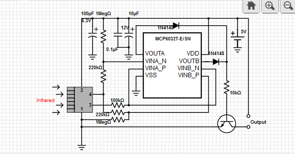
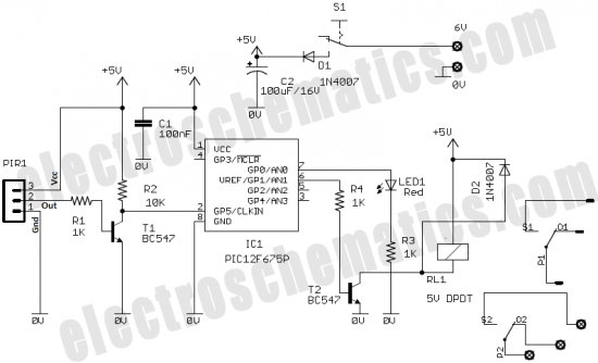
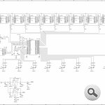
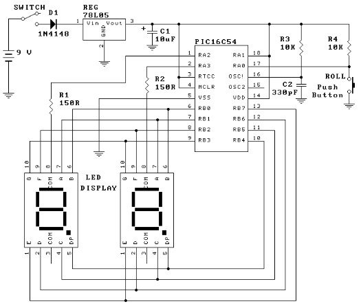
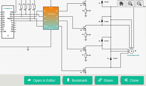
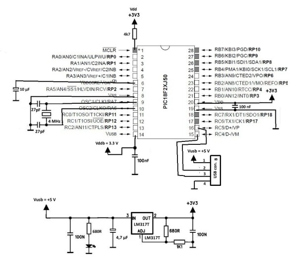
Refer to the schematic below for the explanation which follows immediately below the schematic.

Click on the schematic to get a BIG version.

Nearly all of the actual functions performed are done in software in the two microcontroller chips.  Most of the circuitry is for interfacing the inputs and outputs to the microcontrollers.

First we will examine the inputs and outputs and what interfacing is implemented.  All of the inputs and outputs use screw terminals.

J1 and J2 are 3 terminal connectors for the bed height sensing proximity switches. Each connector supplies ground and +12 volts for the sensors and provides a 5.1 k pull up resistor for the open collector outputs.

J3 is a 4 terminal connector for the tractor driver’s pendant which has a push-button to raise the header quickly and a push-button to lower the header at the end of his turn or to reset a cylinder fault. It provides a ground, two terminals for the up button and one terminal for the down button. The second up button is a spare because we may want’ to ad an up button for the sorter as well as the driver.

J4 is a 3 terminal connector for the photo electric switch that detects cylinder faults.  The connector provides ground and 12 volts dc for the switch, and the signal terminal ties to the up switch on J3.

J5 is a 4 pin terminal, with two ground terminals, (ground and shield),  12 VDC, and signal pin tied to a pull up resistor. The signal pin ties to the input on one of the ULN2067B darlington drivers for buffering as well as the 16F627 microcontroller.

J6 is a 3 terminal connector supplying ground, 12 VDC, and a signal pin for connecting to the pressure transducer. The signal pin does not require a pull up resistor.  The output of the transducer is an analog 0 to 5 volt output.

J7 is a 3 terminal connector for sending the buffered encoder signal and the cut timing voltage to the optical board. It has a ground pin, encoder out pin, and dc 0-5 volt analog signal pin. The 0 to 5 volt dc timing signal pin connects to the wiper of a 5 k resistor connected between +5 volts and ground forming a simple variable voltage divider. The buffered encoder out pin connects to the UL2067B darlington logic driver.

J8 is a 6 pin connector providing outputs for the fast and slow hydraulic lift cylinder valve solenoids, the alarm horn, and the air regulator valve.  The inputs of the darlingtons are directly driven by the microcontroller pins except for the encoder pulses which come directly from the shaft encoder.

J9 is a 6 pin connector which has two terminals for connection to the battery and a terminal for the hydraulic pressure switch. It has output pins providing the B+ for the optical sensor and hydraulic valves.

The terminals that connect to the battery connect to a fuse on the circuit board that provides the 12 volts to power the circuit board itself, the air valve power, the hydraulic valve power, the and all the devices that need 12 volts.

The alternator needs a field connection to the battery to begin putting out voltage. This is accomplished by having a hydraulic pressure switch connect the positive terminal of the batter to the field.  The same connection from the field side of the switch also goes to the hydraulic pressure switch terminal where it drives relay K2s coil directly.  Relay K2 provides a connection from the fuse to the terminals supplying B+ to the optical board, alarm horn, hydraulic valves and to the relay that powers the air valves.

The relay that powers the air valves is driven through a 2N222 transistor which is driven directly by an output pin on the 16F627.  Both relays have a suppression diode across the coil.Re-Doing my Design for a circuit to control an invention using a Microchip PIC microcontroller chips. schematic

The 12 volts from the battery that passes through the fuse and then through relay k2 then travels on to a 3 terminal +5 volt regulator, along with the appropriate bypass and filter caps to provide 5 volts for the microcontroller chips U2 and U3 and all of the pull up resistors.

Chip U2 provides the functions of keeping the header at a pre-determined height above the bed, enabling the air valve B+ supply only when the machine is moving forward, raising the header rapidly if there is a cylinder fault or the up button is pushed on the tractor driver pendant. It also provides an alarm signal for several seconds when the header is raised rapidly.  The darlington used to drive the horn is connected to the chips output pin through a diode so that the air regulating chip can be wire “or’d” to the same darlington input.

Chip U3 Provides the air regulation function and sounds the alarm horn if the air pressure drops too low. A pot is connected from ground to +5 volts with the center lead connected to the analog to digital converter in the chip to obtain an air pressure set point.

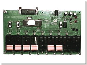
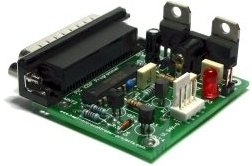
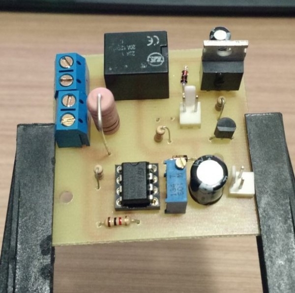
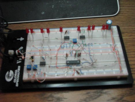
Here is a picture of my breadboard setup for programming the chips.  All of the outputs from the chips go to the LEDs and I just used jumper wires for the inputs and pots for the analog inputs.


For more detail: Re-Doing my Design for a circuit to control an invention using a Microchip PIC microcontroller chips.

The post Re-Doing my Design for a circuit to control an invention using a Microchip PIC microcontroller chips. appeared first on PIC Microcontroller.

Basic circuit for PIC18F24J50 or PIC18F26J50 to work over USB

$
0
0

The basic circuit below will work with any PIC18F2xJ50 microcontroller. You just have to upload the appropriate firmware. Go to Downloads section to find firmware hex files for the microcontroller and the resonator you would like to use. PIC18F24J50 firmware v2.6.3 – all subversions.zip contain the following general use subversions: 4 MHz, 8 MHz, 12 MHz, 16 MHz and 20 MHz, and the following subversions for K8055 adapter: 4 MHz, 8 MHz, 12 MHz, 16 MHz and 20 MHz. PIC18F26J50 firmware v2.7.8 – universal.zip or later enables a wider range of settings. The package contains PC USB Projects HEX Editor v3.0 which makes it possible to set new EEPROM defaults before programming a HEX file.Basic circuit for PIC18F24J50 or PIC18F26J50 to work over USB

Yes, the basic circuit may also serve as a super speed microcontroller programmer (you must manually select option 02 – Super speed K8055 or K8055N programmer in PIC Programmer aplication, or set VID = 10CF (hex)). You just need to use a small piece of PCB to solder a DIP socket and a few resistors and two transistors and two capacitors. Don’t mind about the circuit in the plastic box. It is K8055, but you don’t need it! Use PIC Programmer v2.6 and above for PIC18F2xJ50 microcontroller with v2.2 firmware or later, and previous versions of the application for PIC18F2xJ50 microcontrollers with any versions of the firmwareBasic circuit for PIC18F24J50 or PIC18F26J50 to work over USB schematic

If you would like to use the basic circuit for PIC18F2xJ50 microcontroller programming, just go to subsection 4.b and build the adapter initially intended only for K8055 and K8055N boards. The adapter also works perfectly, if you stick it between the basic circuit DIP socket and the PIC18F2xJ50 microcontroller that you are going to use as a programmer for another PIC2xJ50 microcontroller. You may also use the originally programmed Velleman PIC18F24J50 microcontroller with the basic circuit, if you build it with 4 MHz crystal resonator and appropriate capacitors. See subsection 5.c. to get details on choosing the right capacitor values.


For more detail: Basic circuit for PIC18F24J50 or PIC18F26J50 to work over USB

Current Project / Post can also be found using:

  • neked pic 16 inch lan
  • PIC – Internet projects
  • pic connection to internet
  • pic nasta lans

The post Basic circuit for PIC18F24J50 or PIC18F26J50 to work over USB appeared first on PIC Microcontroller.

Isolated Circuit Digitally Indicates 120-/220-V Line Voltage

$
0
0

or applications such as motor control or power supplies, it’s often necessary to know whether the ac line is at 120 V or 220 V to adjust the operation. The circuit illustrated in the figure monitors the ac line and provides a basic output indicating whether it is at 120 V or 220 V, with the output at the transistor collector going low for 120-V and high for 220-V inputs.

The principle behind the circuit is to make the output of the optocoupler LEDs high enough at 220 V so that it will drive the internal phototransistor to turn transistor Q1 (a standard 2N2222) off to produce a high output, but low enough at 120 V for the phototransistor to turn Q1 on and yield a low output. Optocoupler U1 was chosen because it’s rated and certified for line-voltage applications.

The ac-voltage input goes through resistors R1 and R2 and drives the back-to-back (antiparallel) LEDs inside U1. The LED current, about 1 mA at 120 V and 2 mA at 220 V, is set low to minimize the degradation in current transfer ratio (CTR) over time, which is common with optocouplers (see references). Voltage spikes, which occur at the output of U1 due to the zero crossings where the LEDs aren’t conducting, are narrowest at 220 V as the phototransistor is driven to saturation.

Isolated Circuit Digitally Indicates 120V Line Voltage

At 220-V ac input, the optocoupler’s LEDs turn Q1 off and it has a high output; at 120-V ac, Q1 is on and its output is low.

After RC filtering with a 0.7-second time constant, the average voltage isn’t sufficient to turn on Q1; thus, the output is high. Since the current at 120 V is insufficient to fully drive the phototransistor, its output is pulled up by R3 (after filtering by C1/R4) and drives Q1 into saturation. In effect, Q1 is functioning as a low-gain comparator that’s slowly switching between the high and low states at the “don’t care” line voltages of 150 to 170 V, 50/60 Hz.

When the line is at 120 V, there’s short period of about one second at power on when the output will go high and then low, while the capacitor is being charged. This temporary state may need to be ignored, depending on your monitoring circuit. If the 120-V input will always be at 60 Hz, or the 220 V will always be at 50 Hz, and if the monitoring circuit has some time-measuring capability, C1 can be removed. This results in a square wave that can be used to measure the half-period of the ac input (8.33 ms for 120 V and 10 ms for 220 V). Finally, if the output is coupled into a low-impedance load, it’s a good idea to buffer the output with an emitter-follower transistor stage to reduce the loading.

Edward K. Miguel is now an independent contractor in DeKalb, Illinois, who has worked for 40 years in design and management, specializing in frequency control. He received his BS and MS in EET from Northern Illinois University, with a specialty in quartz frequency control. He can be reached at northerlabs@gmail.com.

References:

Calculate Reliable LED Lifetime Performance in Optocouplers,” Avago Technologies/Broadcom

For more detail:  Isolated Circuit Digitally Indicates 120-/220-V Line Voltage

The post Isolated Circuit Digitally Indicates 120-/220-V Line Voltage appeared first on PIC Microcontroller.

PIC16F690 Microcontroller Circuit- How to Drive an LED Display

$
0
0

In this article, we will show how to drive a 7 segment LED Display using a PIC16F690 microcontroller.

This PIC16F690 microcontroller chip is actually a part of the PIC2 Starter Kit, so we will actually be using this starter kit to drive the LED Display.

A 7 Segment LED Display is an electronic device that contains 8 individual LEDs. Each of the LEDs can either be on or off. Depending on which LEDs are lit determines the character which is displayed. The LED display can show any number from 0 to 9. It can also show many alphabetical characters.

In this project, we will use the PIC16F690 microchip contained in the PIC2 Starter Kit to control the 7 segment LED display so that we can light up whichever segments we want to display whatever characters we want in sequence.PIC16F690 Microcontroller Circuit- How to Drive an LED Display

A 7 segment LED display is a valuable electronic device because used in conjunction with other LED displays, it can function as a numerical display, such as time for a clock, a display for a game scoreboard, or any such other numerical display. So it is a very valuable electronic device to know how to operate.

Using a microcontroller to drive an LED display is much more easy and efficient than not. If we did not have a microcontroller to drive an LED, in order to display different numerical values, we would need someone to manually change which turn on or off different LEDs in the LED display. This would be much less efficient than using a microcontroller. When a microcontroller, in this case a PIC16F690 microcontroller, is connected to an LED display, all we need to do to change the software to display different characters. Changing the hardware, which LEDs are lit, is much more complex and time-consuming and, thus, is simply not efficient.

We will now show how to connect and program the PIC16F690 microcontroller to drive an LED display. Specifically, for this circuit, we will drive one LED display, for simplicity, to count from 0 to 0 and then reset back to 0.

Again, a 7 segment LED sipaly is made up of 8 individual LEDs. Thus, the microcontroller needs enough I/O pins to connect to each of the 8 terminals of the 7 segment LED display. It’s the job of the software to light them in the proper order to create the numbers 0 to 9.

For this project, we will use a common anode LED display, which is a display all the anode leads are common and the cathode leads are not. To understand the difference between common anode and common cathode displays, see What is a 7 Segment LED Display.

Schematic

The schematic of the PIC16F590 microcontroller chip connected to the LED display is shown below:

The PIC16F690 can drive an LED directly from an I/O pin because it can output up to 25ma of current. The whole port can supply 200ma in total maximum. We connect 330Ω resistors to the outputs to limit current so that the LEDs don’t receive too much current and burn out. They are safety current-limiting resistors.

The only connections we need is 5 volts of power to the Vdd pin and to have the Vss pin connected to ground. However, if you plug in the PICkit 2 programmer, you can get power from it and, thus, would not have to make power connections. This reduces more connections.

The PIC16F690 has an internal oscillator that we will run at the default speed of 4MHz. The MCLR master clear reset pin will be set to internal mode so we don’t need any external reset circuitry. Those are both setup in the configuration register of the PIC16F690. We control that configuration in the software.PIC16F690 Microcontroller Circuit- How to Drive an LED Display schematic

Being that the LED display is common anode, all the anodes are tied together (are common). The cathodes are separate and tie down to ground. For an LED to have a complete circuit and turn on, the LED needs to connect to ground. This will happen if its cathode terminal is connected to ground. Thus, if an LED segment is connected to ground it is on. This is why an LED turns on if it is low. If the LED is connected only to the anode’s positive voltage, it is HIGH and off. This will be important when coding, because a 0 will represent an ON LED and a 1 will represent an OFF LED.

Code to Drive LED Display

The code need to drive an LED display is written for the HI-TECH PICC PRO compiler. This can be done in lite mode.

This will sequence 0 to 9 at a 1/2 second rate. It is a common anode display driven by PortC.


For more detail: PIC16F690 Microcontroller Circuit- How to Drive an LED Display

Current Project / Post can also be found using:

  • LED projects using microcontroller
  • problem statement for home automation using PIC micro controllers

The post PIC16F690 Microcontroller Circuit- How to Drive an LED Display appeared first on PIC Microcontroller.

Viewing all 239 articles
Browse latest View live


<script src="https://jsc.adskeeper.com/r/s/rssing.com.1596347.js" async> </script>