Quantcast
Channel: circuit | Battery Guide
Viewing all 239 articles
Browse latest View live

LED Interfacing with PIC Microcontroller: Embedded C program with circuit using pic microcontoller

$
0
0

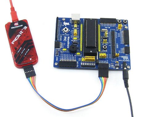
How to interface LED with Microchip’s PIC microcontroller? How to connect LEDs to a PIC microcontroller? LED interfacing is the stepping stone for microcontroller development. This is a simple embedded program for PIC 16F877A to interface LEDs, suitable for beginners who wish to study basics of embedded microcontroller programming. The program is developed through Micro C compiler, one of the best solutions for embedded programming in PIC family. It is compatible for Windows XP and Windows 7 platforms and comes with internal burning tools. This PIC circuit is a beginner circuit, do this PIC project to explore the world of microcontrollers.

LED Interfacing with PIC Microcontroller Embedded C program with circuit using pic microcontoller

Algorithm for implementing this PIC project

  1. Specify the output port [here PORT B is used to connect LEDs, So TRISB=0×00; comment is used for specifying the output port]
  2. Start infinite loop [while(1){} is used here]
  3. Pass 0×00 value to the output port [PORTB=0×00;]
  4. Provide a delay. The inbuilt delay function, that is delay_ms(); gives some delay. You can change the duration of LED blinking by giving any value to the calling field of this function. For example delay_ms(1000); will give 1 second delay.
  5. Pass 0xFF value to the output port [PORTB=0xFF;]
  6. Provide a delay [delay_ms(1000);]
  7. Repeat the loop.

LED interfacing embedded C Program for PIC microcontroller

void main()
{
TRISB=0×00;
while(1)
{
PORTB=0×00;
delay_ms(1000);
PORTB=0xFF;
delay_ms(1000);
}
}
The while loop will execute infinitely. So all 8 LEDs connected to PORT B starts blinking with 1 sec delay. This program is tested and verified under i-St@r laboratory.

Read further: Loops in C programming

LED Interfacing with PIC Microcontroller Embedded C program with circuit using pic microcontoller

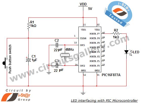
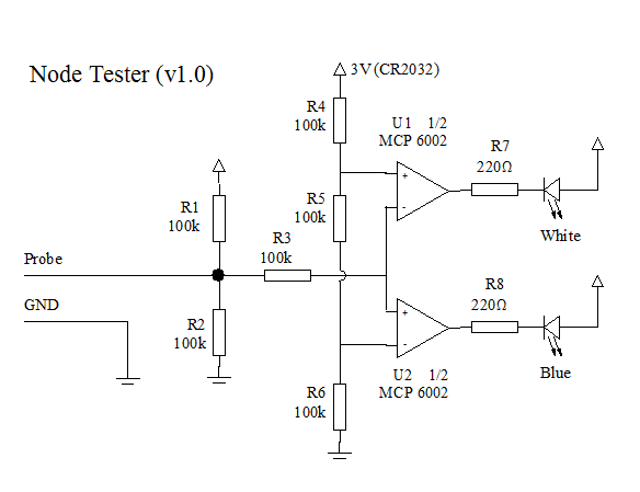
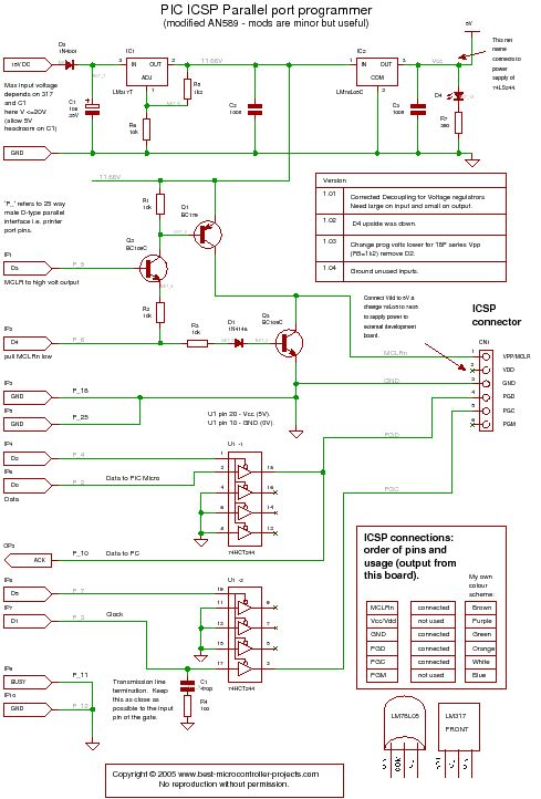
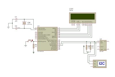
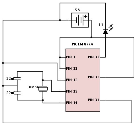
Circuit diagram of PIC project

What is Next?

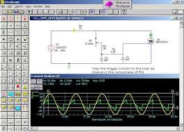
Now we want to build a .HEX file for this program and then burn it in to our PIC microcontroller..! Dig further


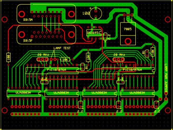
For more detail: LED Interfacing with PIC Microcontroller: Embedded C program with circuit

The post LED Interfacing with PIC Microcontroller: Embedded C program with circuit using pic microcontoller appeared first on PIC Microcontroller.


Microcontroller In Circuit Serial Programming (ICSP) with Microchip PIC

$
0
0

In Circuit Serial Programming is a method of directly programming a Microchip PIC or Atmel AVR while in they are connected to a circuit, as opposed to programming the chip ahead, and only then soldering it to a circuit. There are many benefits to ICSP, but also some important design considerations which I will try to highlight.

In circuit programming has many advantages:

  • It shortens the development cycle – it is really annoying to take a chip out of the board each time it needs to be reprogrammed, and it’s even much harder with SMD.
  • Allows customer and in field firmware upgrades
  • Calibrate the system during manufacturing or in the field
  • Assign unique ID \ serial number to productMicrocontroller In Circuit Serial Programming (ICSP) with Microchip PIC

How to prepare your circuit to work with ICSP?

The programmer uses serial signaling scheme to program the chip in circuit. The signaling is carried through the programming clock (PGC or ICSPCLK) and the programming data (PGD or ICSPDAT) pins. In addition, the MCLR/VPP pin is used as either a high voltage programming signal or an attention indicator to the device.

Wherever application allows, use dedicated pins for ICSP. It will save you much trouble. Not sharing a pin both for ICSP and I/O for example, minimizes the preparation work which needs to be done to allow ICSP.

Often, and especially true with low pin devices, it is not possible to dedicate the 3 needed pins just for ICSP, and when want them to have dual functionality.

In this case:

1. Isolate Vpp from the circuit by using a Schotkey diode and an R/C. NOTE: in some devices, like the PIC12F629, this pin will be driven to about 13 volts by the programmer while programming the device. Make sure whatever is connected to the Vpp pin can sustain this voltage level, or isolate it with an appropriate resistor or a Schotkey diode.Microcontroller In Circuit Serial Programming (ICSP) with Microchip PIC schematic

2. Isolate ICSP_Clock and ICSP_Data from the rest of the circuit. The isolation method is application specific, which unfortunately means there is no ready recipe.  Often, a resistive isolation works fine. Recommended resistor values are 1k to 10k.

3. Physically locate the ICSP header as close as possible to the programmed chip, to reduce attenuation.

Common Microchip PIC ICSP layouts

Additional reading and references

  • Microchip PICKit 2  manual
  • Microchip In-Circuit Serial Programming™ (ICSP™ ) Guide
  • ICSP in wikipedia


For more detail: Microcontroller In Circuit Serial Programming (ICSP) with Microchip PIC

The post Microcontroller In Circuit Serial Programming (ICSP) with Microchip PIC appeared first on PIC Microcontroller.

Building a simple circuit probe

$
0
0

The Goals

Sometimes you need to check one circuit and test some of its nodes. Usually a tester in voltage mode is a good solution, but it has a pair of problems. First, it measures about zero both when the node is driven at zero volts and when the node is floating (not driven at all). Second, it gives the information on the tester display, so you need to take the view from the circuit to the tester to check the voltage.
The proposed circuit somewhat qualifies as a logic probe. It should give no indication when the node is not being driven and it should give a different indication when the node is driven at high or a low voltage.


A lot of logic probes are not self powered. They rely on the circuit supply to operate. In my case I would like the probe to be usable also a as a continuity tester. If we set ground in one point of the circuit and we probe another point, the continuity can be detected between both points because a low level will be driven even if the circuit is not powered at all.

The Circuit

The following figure shows the schematic of the circuit.
Building a simple circuit probe
Probe Schematic
The circuit is powered with a 3V CR2032 battery. When the probe is not connected to anything, the probe voltage, as set with R1 and R2 will be 1.5V. As both Operational Amplifiers (MCP6002) have very low bias current (1pA), no voltage drops on R3 and 1.5V is also seen on the non inverting input of U2 and on the inverting input of U1.
Resistors R4, R5 and R6 define a voltage divider that sets 1V on the inverting input of U2 and 2V on the non inverting input of U1. With 1.5V on the probe, both operationals saturate at high level (3V) so both LEDs are OFF.
If we set the probe tip to a voltage below 1V (The trip point of U2), U2 will saturate at low level and the Blue LED will turn ON. In a similar way, if the probe tip voltage is set above 2V (The trip point of U1), U1 will saturate at low level and the White LED will turn ON. I know white is a strange color for high level. A red color will be better buy I had no red LEDs similar to the blue one at hand.
Operational Amplifiers are not the best suited components for this project. As they are used as compactors, a dual comparator could be better in this case. The choice of the MCP6002 dual opamp was only because I had them available.

For more detail: Building a simple circuit probe

The post Building a simple circuit probe appeared first on PIC Microcontroller.

MP3 player on a chip from On Semi

$
0
0

ON Semiconductor, driving innovation in energy efficiency, has introduced a new MP3 capable device to support both record and playback in portable MP3 audio applications where there is a strong requirement for miniaturization, reduced bill of materials (BoM) and reduced cost. The LC823430TA audio processing system provides a single-chip solution by integrating digital signal processing (DSP) circuitry for MP3 encoding and decoding, and analog blocks such as audio analog-to-digital conversion (ADC) and digital-to-analog conversion (DAC).

The LC823430TA is a housed in space-saving 128-pin TQFP package with an overall height of just 1.2 mm maximum. The new device features segment-type LCD-connectable driver circuitry with two separate versions supporting either eight common by 18 segment (USB model) or four common by 36 segment (non-USB model) displays. Various flash memory interfaces such as SD/MMC and USB 2.0 device interface are also embedded within the design to provide further important space and BoM savings.

In addition to MP3 encoding and decoding, the LC823430TA’s embedded DSP provides a noise cancellation feature to enhance the audio quality of recorded data by eliminating background noise such as wind or HVAC noise. A variable speed playback function is also included to allow audio data to be played back faster or slower without changing pitch. Further embedded analog circuitry provides a speaker and microphone amplifier and a programmable gain amplifier (PGA) with digital auto level control (ALC) for more consistent playback.

MP3 player on a chip from On Semi

ON Semiconductor has introduced an MP3 record and playback chip with almost everything needed in an audio device except flash memory.

The 16x16mm chip, dubbed LC823430TA audio processing system, has DSP for MP3 encode and decode, DACs and microphone pre-amps, and DACs and both speaker (300mW) and headphone drivers.

There are also interfaces for eSD and eMMC cards for flash bulk storage, USB2.0, and a segment-type LCD.

A second version of the chip sacrifices the USB for a more complex LCD capability.

“In addition to MP3 encoding and decoding, the LC823430TA’s embedded DSP provides a noise cancellation feature to enhance the audio quality of recorded data by eliminating background noise such as wind or air conditioning noise,” said On. “A variable speed playback function is also included to allow audio data to be played back faster or slower without changing pitch. Digital auto level control provides more consistent playback.”

Unusually, there is a separate real-time clock that runs with an external 32.738kHz crystal. This, and several of the analogue blocks, the USB phy and various SRAMs, are on isolated power domains and can be powered down through registers to cut power consumption.


For more read: MP3 player on a chip from On Semi

The post MP3 player on a chip from On Semi appeared first on PIC Microcontroller.

Circuit Simulator

$
0
0

How to use this

When the simulator starts up you will see an animated schematic of a simple LRC circuit. The green colour indicates positive voltage. The grey colour indicates ground. A red colour indicates negative voltage. The moving yellow dots indicate current.

To turn a switch on or off, just click on it. If you move the mouse over any component of the circuit, you will see a short description of that component and its current state in the lower right corner of the window. To modify a component, move the mouse over it, click the right mouse button (or control-click if you have a Mac) and select “Edit”. You can also access the edit function by double-clicking on a component.

There are three graphs at the bottom of the window; these act like oscilloscopes, each one showing the voltage and current across a particular component. Voltage is shown in green, and current is shown in yellow. The current may not be visible if the voltage graph is on top of it. The peak value of the voltage in the scope window is also shown. Move the mouse over one of the scope views, and the component it is graphing will be highlighted. To modify or remove a scope, click the right mouse button over it and choose “remove” from the menu. There are also many other scope options in this context menu. To view a component in the scope, click the right mouse button over the component and select “View in Scope”.

Circuit Simulator

The “Circuits” menu contains a lot of sample circuits for you to try.

Some circuits, eg Basics->Potentiometer, contain potentiometers or variable voltage sources. These can be adjusted using sliders that are added to the right hand tool bar, or by positioning the mouse pointer over the component and using the scroll wheel.

You can get a blank circuit by choosing “Blank Circuit” from the “Circuits” menu. You will need to add at least one voltage source to start the simulator.

To add components or a wire choose one of the “Add….” options from the “Draw” menu. Note that common components have keyboard short-cuts to select their add mode. When in add mode the cursor changes to a “+”. Click and drag the mouse to add a component.

Components may be moved and resized in the selection mode. When in selection mode the cursor changes to an arrow. Choose “Select/Drag Sel” from the “Draw” menu or press “space”, or press “escape” to go in to selection mode. Hovering over a component will highlight it and show information about that component in the info area. Clicking and dragging on a component will move the component. If you click and drag on the square handles or hold down the ctrl key this will resize the component and move the terminals.

For more detail: Circuit Simulator

The post Circuit Simulator appeared first on PIC Microcontroller.

How To Select a Capacitor

$
0
0

Capacitors   

Capacitors are two-terminal components used for filtering, energy storage, voltage spike suppression, and many other applications. In their simplest form, they consist of two parallel plates separated by an insulating material called a dielectric. Capacitors store electrical charge. The unit of capacitance is Farad (F), attributed to Michael Faraday who was a pioneer in using capacitors for practical applications.

Capacitors can either be polarized or non-polarized. Polarized capacitors — nearly all electrolytic and tantalum capacitors — can only be connected one way in a circuit: if the “-” terminal goes above “+” terminal, it could lead to a short. Non-polarized capacitors — ceramic, mica, and film capacitors — can be connected either way in a circuit, so they are suitable for AC.

Even though capacitors are so commonly used, it can be tricky to select one for your project. While you might know what capacitance or voltage rating your project requires, capacitors have lots of other characteristics — such as polarization, temperature coefficient, stability, equivalent series resistance (ESR) and so on — that might make them a great (or poor) choice for your project. The most popular types of capacitors are presented below with this in mind.

How To Select a Capacitor
TYPES
There are several different types of capacitors which differ by polarity, performance and cost. Below are some of the common capacitor types: aluminum electrolytic, ceramic, tantalum, film, mica and polymer capacitors, along with their characteristics, applications, package information as well as info on part selection.

I. Aluminium Electrolytic Capacitors 

Characteristic: Aluminum Electrolytic Capacitors are polarized, so they cannot be used with AC. They can achieve high capacitance value but with large variations, typically 20%.

Applications: These are useful in applications which do not need tight tolerances or AC polarization. They are most commonly used in power supplies for decoupling purposes, i.e. to reduce voltage ripple reaching the circuit. They are also used widely in DC/DC switching voltage converters.

Package: Available in through-hole as well as surface mount package.

Part Selection:
Through-Hole: 6.3V rated Panasonic’s ECA-0JM series for 220µF to 22000µF.
50V rated Panasonic’s ECA-1HM series for 10µF to 3300µF.

Surface Mount:
 6.3V rated Panasonic’s EEE-HD0J series for 330µF to 1000µF.
50V rated Panasonic’s EEE-HD1H series for 1µF to 100µF.

II. Ceramic Capacitors

Characteristic: There are two main types of ceramic capacitors: Multi-layer chip capacitors (MLCCs) and ceramic disc capacitors. MLCCs are very widely used in electronic devices and are popular because they have high stability and low losses. They have lower Equivalent Series Resistance (ESR) and variation compared to electrolytic or tantalum capacitors but can achieve lower capacitance (only up to a few µF) . Because of high packing densities, MLCC capacitors provide a size advantage and are great for printed circuit boards (PCBs).

Applications: Since these are not polarized, they can be be used with AC. They are widely used as a ‘general-purpose’ capacitor and used for high frequency blocking, filtering, oscillator tuning and EMI suppression.
For more detail:  How To Select a Capacitor

The post How To Select a Capacitor appeared first on PIC Microcontroller.

Voltage-controlled attenuators characterised

$
0
0

Product Description

RFMD’s RFSA3013 is a fully monolithic analog voltage controlled attenuator (VCA) featuring exceptional linearity over a minimum temperature compensated 30dB gain control range. It incorporates a revolutionary new circuit architecture to solve a long standing industry problem: high IP3, high attenuation range, low DC current, broad bandwidth and temperature compensated linear in dB control voltage characteristic. This voltage controlled attenuator is controlled by a single positive control voltage with on-chip DC conditioning circuitry. The slope of the control voltage versus gain is selectable. The RFSA3013 draws a very low 1mA current and is packaged in a small 3mmx 3mm QFN. This attenuator is matched to 75Ω over its rated control range and frequency with no external matching components required. Typical VCAs in this performance category have poor inherent attenuation versus temperature and poor nonlinear attenuation versus control voltage characteristics. To correct these shortcomings, other VCAs require extensive off chip analog support circuitry that consume valuable PCB area and additional DC power. This game changing product incorporates the complete solution in a small 3mm x 3mm QFN package that reduces the footprint by 20X in area and reduces the DC power by 10X over conventional PIN diode approaches.

Features

  • Patent Pending Circuit Architecture
  • Broadband 50MHz to 3000MHz Frequency Range
  • 30dB Attenuation Range
  • +50dBm IIP3 Typical
  • +80dBm IIP2 Typical
  • Low Distortion -65dBc CSO and -70dBc CTB for 112 Channel 39dBmV Input
  • High 1dB Compression Point >+30dBm
  • Low Supply Current 1mA Typical
  • 5V Power Supply
  • Linear in dB Control Characteristic
  • Internal Temperature Compensation
  • Class 1C ESD (1000V)
  • Complete Solution in a Small 3mm x 3mm, QFN Package
  • 3.3V Version Available, RFSA3023

Voltage-controlled attenuators characterised

RFMD’s RFSA3013 and RFSA3023 monolithic analogue voltage-controlled attenuators (VCAs) are designed for good linearity over a 30dB minimum gain control range.

These VCAs also feature internal temperature compensation that provides an attenuation profile highly insensitive to temperature changes.

Each VCA is controlled by a single positive control voltage with on-chip DC conditioning circuitry.

The slope of the control voltage versus gain is selectable.

The VCAs have been characterised for 75ohm CATV applications over the full attenuation and frequency ranges with no external matching components required.

The components are offered in a 3mm x 3mm QFN package.


For more read: Voltage-controlled attenuators characterised

The post Voltage-controlled attenuators characterised appeared first on PIC Microcontroller.

A pic programmer circuit based on AN589 using pic microcontoller

$
0
0

AN589 is microchip’s application note for a parallel port pic programmer circuit which I chose as I wanted something reliable to get up and running quickly.

Note: This page is left on site for legacy information that is applicable to older computers. These days PCs and laptops have only a USB interface so a parallel programming circuit is not useful. instead you should be using a PicKit3 (or maybe PicKit2) programmer which interfaces to the MPLAB X IDE and works well.

A pic programmer circuit based on AN589It is really quite a simple circuit and its main objective is to provide ICSP connections to your pic microcontroller.

Note: That the PGM signal is not provided – it’s not really necessary anyway as you can turn off PGM mode by programming the chip.  For first use of a chip you will need to pull the PGM line low as PGM is enabled by the manufacturer.

PIC Programmer Circuit diagram

Disclaimer : If you build this circuit you must double check each connection to the parallel port cable to avoid damage to your computer. This includes checking for shorts between each pin at the parallel port on your circuit. For initial testing it is best if you use a spare (old computer). Building this project is your own responsibility and I can not be held responsible for any damage to your computer.

A pic programmer circuit based on AN589

Modifications

It has a few modifications that are useful and easy to do:

    • Transmission line termination – lets it work over a long cable.
    • LM317 voltage regulator to get 11.6 volts and protect the circuit
    • Power supply steering diode (stops you reverse connecting the supply).
    • Changed LM340-5 to 3pin 100mA LM78L05.
    • ICSP connector.
    • An LED to show that power is applied.
    • Changed 74LS244 to 74HCT244 because I had one handy!
    • Standard 10k resistors instead of 2k – just easier if they are all the same.


For more detail: A pic programmer circuit based on AN589

The post A pic programmer circuit based on AN589 using pic microcontoller appeared first on PIC Microcontroller.


Molex designs capacitive touch switch into washing machine

$
0
0

A global leader in membrane switch and capacitive user interface technology. With manufacturing capabilities strategically placed around the world, Molex provides local sourcing; engineering and design support in ISO9001, ISO 14000, and TS16949 certified facilities. Fully equipped reliability labs in each location qualify products prior to final tooling and can provide in-depth analysis.

Our capabilities include double-sided circuits for space-constrained applications; LED bonding for high-volume applications; and vertically integrated assemblies including PCBs, copper flex circuits, connectors and cables. Our solutions directly address today’s electromechanical engineering requirements in the appliance, consumer, automotive, industrial, datacom, transportation, and medical industries.

Molex is working with a multinational washing machine manufacturer to develop capacitive touchpad panels for two high-end Class-A energy saving washing machines.

Molex designs capacitive touch switch into washing machine

The capacitive switch panel designs incorporate solid-state circuitry in a robust interface that is highly resistant to multiple key presses, water, dirt, contaminants and EMI.

Molex capacitive overlays and panels allow easy appliance cleaning and are available in a variety of cosmetic options, including in-mould decoration (IMD), glass or virtually any non-conductive material.

“Capacitive switch technology offers a proven upgrade to mechanical controls in electronic user interfaces,” said Steve Fulton, engineering manager, Molex.

The washing machines feature multiple wash cycles and will require numerous tightly spaced capacitive key sensors and icons.

“The washing machine user panels encapsulate imaginative ideas and robust engineering for enhanced functionality, with exceptional product reliability and energy savings,” said Fulton.

A single 44-pin microcontroller handles all panel functionality.

Universal Asynchronous Receiver/Transmitter communication for sensor reporting and lighting control ensures consistent responsiveness and panel lighting levels in the user-controlled bright and dim modes.

The power button has been integrated into the Molex capacitive panels to provide additional power savings when the appliance is not in use; a dead front appearance hides the icons until the power button is activated.


For more read:Molex designs capacitive touch switch into washing machine


The post Molex designs capacitive touch switch into washing machine appeared first on PIC Microcontroller.

ADI squeezes quad DAC into small 3mm x 3mm package

$
0
0

The AD5686, a member of the nanoDAC+™ family is a low power, quad, 16-bit buffered voltage output DAC. The device includes a gain select pin giving a full-scale output of 0V to VREF (gain = 1) or 0V to 2VREF (gain = 2). The device operates from a single 2.7 V to 5.5 V supply, is guaranteed monotonic by design, and exhibits less than 0.1% FSR gain error and 1.5 mV offset error performance. The device is available in a 3 mm × 3 mm LFCSP and a TSSOP package.

The AD5686 also incorporates a power-on reset circuit and a RSTSEL pin that ensures that the DAC outputs power up to zero scale or midscale and remain at that level until a valid write takes place. Each part contains a per-channel power-down feature that reduces the current consumption of the device to 4 µA at 3 V while in power-down mode.

The AD5686 employs a versatile SPI interface that operates at clock rates up to 50 MHz, and all devices contain a VLOGIC pin intended for 1.8 V/3 V/5 V logic.

FEATURES and BENEFITS


  •     High relative accuracy (INL): ±2 LSB maximum @ 16 bits
  •     Tiny package: 3 mm × 3 mm, 16-lead LFCSP
  •     Total unadjusted error (TUE): ±0.1% of FSR maximum
  •     Offset error: ±1.5 mV maximum
  •     Gain error: ±0.1% of FSR maximum
  •     High drive capability: 20 mA, 0.5 V from supply rails
  •     User selectable gain of 1 or 2 (GAIN pin)
  •     Reset to zero scale or midscale (RSTSEL pin)
  •     1.8 V logic compatibility
  •     50 MHz SPI with readback or daisy chain
  •     Low glitch: 0.5 nV-sec
  •     Robust 4 kV HBM and 1.5 kV FICDM ESD rating
  •     Low power: 1.8 mW at 3 V
  •     2.7 V to 5.5 V power supply
  •     −40°C to +105°C temperature range

ADI squeezes quad DAC into small 3mm x 3mm package

Analog Devices has a range of quad 16- and 12-bit 3V/5V digital-to-analogue converters (DACs) in its smallest 3mm x 3mm package.

The AD5686/96 nanoDAC+ quad DACs offer the supplier’s best DC performance specitiofcation. INL is ±2LSB max, offset error is  ±1.5mV max and gain error is ±0.1% max in the LFCSP package with SPI or I²C interface options.

Applications are likely to include PLC (programmable logic controller) I/O cards, digital oscilloscopes, signal generators and optical modules that require low power, rail-to-rail.

The supplier’s AD5316R and AD5317R quad 10-bit nanoDACs offer similar DC performance to the AD5686/96, robustness up to 4kV ESD and low drift on-chip 2.5V voltage reference in a 3mm x 3mm footprint.

View the AD5686 D/A converter product page, order samples and eval boards and download the data sheet: http://www.analog.com/ad5686


For more read: ADI squeezes quad DAC into small 3mm x 3mm package

The post ADI squeezes quad DAC into small 3mm x 3mm package appeared first on PIC Microcontroller.

TI adds spatial audio to tablet computers

$
0
0

Texas Instruments’ LM48901 is a quad Class D amplifier that utilizes Texas Instruments’ proprietary spatial sound processor to create an enhanced sound stage for portable multimedia devices. The Class D output stages feature Texas Instruments’ edge rate control (ERC) PWM architecture that significantly reduces RF emissions while preserving audio quality and efficiency. The LM48901’s flexible I²S interface is compatible with standard serial audio interfaces. A stereo differential-input ADC gives the device the ability to process analog stereo audio signals.   LM48901 Datasheet

  Features

  • Spatial sound processing
  • I²S compatible input
  • Differential-Input Stereo ADC
  • Edge rate control reduces EMI while preserving
    audio quality and efficiency
  • Paralleled output mode
  • Short circuit and thermal overload protection

Applications

  • Laptops
  • Tablets
  • Desktop computers
  • Sound bars
  • Multimedia devices
  • MP3 player accessories
  • Docking stations

TI adds spatial audio to tablet computers

Texas Instruments has introduced an IC and design software that simplifies the implementation of spatially-enhanced audio in portable multi-speaker products.

Called the LM48901, the chip includes a sound processor and four 2W Class D amplifiers, and up to four of the ICs can be run together do drive up to 16 speakers. http://www.ti.com/spatial-pr

The chip introduces differential time delays and selectively filtering to direct sound and add psychoacoustic clues to the audio streams according to parameters pre-calculated by the accompanying design tool.

“We use beam forming and cross-talk cancellation to create a virtual headphone,” TI spatial audio engineer Eric Eklund told Electronics Weekly. “Than a head-related transfer function gives the impression of sound all around.”

So what does it sound like?

“I can get it to sound like sound is coming from any angle within 120° in front of you from speakers in a tablet computer,” said Eklund. “If you shut your eyes, you can not point to the actual speakers.”

To set-up the system for a particular product, engineers type the system geometry into the design tool.

“In programming the device, you input the position of the speakers and then you input the position of the listener,” said Eklund. “It is best if you can place the speakers in a horizontal line. It doesn’t have to be perfectly straight, but the closer the better.”

“If customer is using four speakers in their middle-range product, they can re-use almost all of their design effort if they make a high-end version with eight speakers,” he added.

At power-up, the parametric data is downloaded into the chip or chips, cascading through them if there is more than one.

In operation, all four, eight or 16 channels run in parallel with their individual pre-programmed delays and filter characteristics creating the final sound stage.


For more read: TI adds spatial audio to tablet computers

The post TI adds spatial audio to tablet computers appeared first on PIC Microcontroller.

Iterated-map circuit creates chaos

$
0
0

the Design Idea circuit shown below is a simple implementation of an iterated unimodal map, reminiscent of the logistic or Verhulst map encountered in the study of nonlinear dynamics. It is useful to show chaotic discrete-time dynamics to students, or as a random number generator. Specifically, the circuit implements: Vk+1 = rF(Vk), where F is a nonlinear unimodal function (a “bump”), implemented by the circuit in the dashed box. The response of this circuit is shown in the Vout vs. Vin plot.

r is a gain factor provided by U1b. U1a and U3a are simply buffers. During the low phase of the clock signal, the output voltage of the nonlinear function is stored on C1. When the clock switches to high, this voltage is transferred to C2, and then used as the next input to the unimodal function. The supply voltage is 12V. S3 (¼ 4066) is used as an inverter.

Iterated-map circuit creates chaos

For low gain settings (r), the iterates have the origin, zero volts, as stable equilibrium: V* = rF(V*). By increasing the gain, the circuit moves from a stable equilibrium to n-periodic oscillations. The iterates of an n-periodic oscillation can be seen as equilibria of the n-iterated map, e.g., V* = rF(rF(rF(V*))) for 3-periodic oscillations. This is shown in the first oscilloscope screenshot, for r=4.7

For More Details : Iterated-map circuit creates chaos

The post Iterated-map circuit creates chaos appeared first on PIC Microcontroller.

Interfacing DS1307 to PIC Microcontroller with C code and Circuit Diagram

$
0
0
This tutorial will help you to interface DS1307 RTC with PIC16F877 Microcontroller. The project is compiled in CCS Compiler and simulated with Proteus. The Real Time Clock is interfaced with PIC controller via I2C. I2C is a 2 wire communication protocol. I2C is used for moving data from one device to another simply and quickly. It is a serial, synchronous, Bi-Directional protocol, the data is synchronised  with clock through SCL pin and it controls when data is changed and when it should be read. All device is controlled by master device’s clock, No data is transferred in the absence of clock.
As mentioned above data is bi-directional, master device can both transmit and receive data. The serial data (SDA) and Serial Clock (SCL) pins must be pulled up with resistors, the value of resistors determine the speed of communication.
Interfacing DS1307 to PIC Microcontroller with C code and Circuit DiagramEmbedded C Program for DS-1307 I2C Communication
#include <16F877.h>
#include <lcd_4bit.c>
#use delay(clock=4000000)
#define RTC_SDA  PIN_C4
#define RTC_SCL  PIN_C3
#use i2c(master, sda=RTC_SDA, scl=RTC_SCL)
void rtc_get_time() ;
int convert(int k);
int sec,min,hr,k[20],z,k1[20];
int day1,date,month,year;
void main()
{SETUP_ADC(ADC_OFF);
lcd_init();
while(1)
{rtc_get_time();
lcd_cmd(0x80);
sprintf(k,”%02d:%02d:%02d”,hr,min,sec);
lcd_array(k);
lcd_cmd(0xc0);
sprintf(k1,”%02d:%02d:%02d “,date,month,year,);
lcd_array(k1);
lcd_cmd(0xc9);
switch(day1)
{
case 1: lcd_str(“Sunday”);
break;
case 2: lcd_str(“Monday”);
break;
case 3: lcd_str(“Tuesday”);
break;
case 4: lcd_str(“Wednesday”);
break;
case 5: lcd_str(“Thursday”);
break;
case 6: lcd_str(“Friday”);
break;
case 7: lcd_str(“Saturday”);
break;
} }}
void rtc_get_time()
{
  i2c_start();
  i2c_write(0xD0);
  i2c_write(0x00);
  i2c_start();
  i2c_write(0xD1);
  sec = i2c_read();
  min = i2c_read();
  hr  = i2c_read();
 day1=i2c_read();
 date=i2c_read();
 month=i2c_read();
 year=i2c_read(0);
  i2c_stop();
 Interfacing DS1307 to PIC Microcontroller with C code and Circuit Diagram
 sec= convert(sec);
 min= convert(min);
 hr= convert(hr);
 day1= convert(day1);
 date= convert(date);
 month= convert(month);
 year= convert(year);
 z=’a’;
if(hr>12)
{
hr=hr-12;
z=’p’;
}
}
int convert(int k)
{
int a0,a1,a;
 a0=((k&0x0F));
 a1=k>>4;
  a=((a1*10)+a0);
  return a;
}
Above shows  a simple program to read the Time value from DS-1307 IC. RTC Ds-1307 consumes very low power(500nA), so it can be backup by a battery for power failure issues.   For DS1307, the device address is D0. The data, for example seconds value, located in the zeroth register is taken and converted from BCD to integer, before displaying it on the LCD. We can also write the Time value to Ds1307 registers one by one.

The post Interfacing DS1307 to PIC Microcontroller with C code and Circuit Diagram appeared first on PIC Microcontroller.

Basic PIC circuit is not working

$
0
0

I have just begun in the world of micro-controllers, and the first micro-controller. I chose to work with was the PIC from Microchip. The PIC I am using is the PIC16F877A. I am using MPLAP IDE and HI-TECH C. I am trying to make an extremely simple program that turns on an LED. This is the code I am using:

Basic PIC circuit is not working#include<htc.h> #define _XTAL_FREQ 8000000 __CONFIG(UNPROTECT & PWRTDIS & WDTDIS & HS & LVPDIS); int main() { TRISB0 = 0; RB0 = 1; while(1);}

When I hookup the PIC to my circuit the LED does not turn on.

A few other notes about my circuit:

  • I am using a 9 volt battery hooked up to a 7805 regulator for the power supply
  • I have measured the voltage coming from pin RB0 with a multimeter and it measures 0.0V.

Basic PIC circuit is not working Schematic

  • If there is no problem with my circuit I could have programmed the chip wrong
  • My capacitors hooked up with my crystal are 22pf not 22uf
  • I have put 100uf capacitors between pins 11 and 12 and between 31 and 32


For more detail: Basic PIC circuit is not working

The post Basic PIC circuit is not working appeared first on PIC Microcontroller.

Maxim claims Class D amps will simplify audio design

$
0
0

Description

The MAX98355A/MAX98355B are digital pulse-code modulation (PCM) input Class D power amplifiers that provide Class AB audio performance with Class D efficiency. These ICs offer five selectable gain settings (3dB, 6dB, 9dB, 12dB, and 15dB) set by a single gain-select input (GAIN).

The digital audio interface is highly flexible with the MAX98355A supporting I²S data and the MAX98355B supporting left-justified data. Both ICs support time division multiplexed (TDM) data. The digital audio interface accepts sample rates ranging from 8kHz to 96kHz for all supported data formats. The ICs can be configured to produce a left channel, right channel, or (left + right)/2 output from the stereo input data. The ICs operate using 16/24/32-bit data for I²S and left justified modes as well as 16-bit data with up to four slots when using TDM mode. The ICs eliminate the need for the external MCLK signal that is typically used for PCM communication. This reduces EMI and possible board coupling issues in addition to reducing the size and pin count of the ICs.

The ICs also feature a very high wideband jitter tolerance (12ns typ) on BCLK and LRCLK to provide robust operation.

Active emissions-limiting, edge-rate limiting, and overshoot control circuitry greatly reduce EMI. A filterless spread-spectrum modulation scheme eliminates the need for output filtering found in traditional Class D devices and reduces the component count of the solution.

Key Features

  • Single-Supply Operation (2.5V to 5.5V)
  • 3.2W Output Power into 4Ω at 5V
  • 2.2mA Quiescent Current
  • 92% Efficiency (RL = 8Ω, POUT = 900mW, VDD = 3.7V)
  • 25µVRMS Output Noise (AV = 15dB)
  • Low 0.013% THD+N at 1kHz
  • No MCLK Required
  • Sample Rates of 8kHz to 96kHz
  • Supports Left, Right, or (Left + Right)/2 Outputs
  • Sophisticated Edge Rate Control Enables Filterless Class D Outputs
  • 77dB PSRR at 217Hz
  • Low RF Susceptibility Rejects TDMA Noise from GSM Radios
  • Extensive Click-and-Pop Reduction Circuitry
  • Robust Short-Circuit and Thermal Protection
  • Available in Space-Saving Package: 1.345mm x 1.435mm WLP (0.4mm Pitch)

Maxim claims Class D amps will simplify audio design

Maxim Integrated has introduced a couple of digital-input Class D power amplifiers that it claims will simplify audio designs by eliminating complicated programming.

“Audio design can be simplified because internal circuitry in the MAX98355/MAX98356 detects the input clock and automatically calculates the sample rate.

According to the supplier, this reduces complicated programming and the need for system software support.

“These digital-input Class D amplifiers make system design nearly plug and play,” said Robert Nicoletti, applications manager at Maxim Integrated.

The MAX98355 (pulse-code modulation, PCM) and MAX98356 (pulse-density modulation, PDM) offer high jitter tolerance with low 0.013% THD+N at 1kHz and 99dB dynamic range.

Power efficiency is 92% at RL = 8?, POUT = 900mW, V­DD = 3.7V.

The chips are available in a 9-pin WLP package (1.345mm x 1.435mm x 0.64mm).


For more read: Maxim claims Class D amps will simplify audio design

The post Maxim claims Class D amps will simplify audio design appeared first on PIC Microcontroller.


PIC microcontroller Beginner’s guide: Basic connection circuit

$
0
0
What is a pic microcontroller? The PIC microcontroller is a low cost ‘computers on a chip’ manufactured by Microchip. They allow electronic designers and hobbyists impart intelligence and logic to a single chip for special purpose applications and products. The PIC microcontroller programming is done using the popular software ‘Mikro C’. This powerful yet easy to program into a 40-pin package is upwards compatible with the PIC16C5X, PIC12CXXX and PIC16C7X devices.
PIC microcontroller Beginner’s guide Basic connection circuit
 How to program microcontroller? Which is the program for microcontroller? These are the commonly asked questions by microcontroller beginners. Here we are going to explore the world of microcontroller, microcontroller programming and embedded systems with PIC16F877A. It is has five ports- port A, port B, port C, port D and port E.
An embedded system design is easy with the help of embedded C programming. Let’s start studying about microcontroller and embedded C programming for microcontroller PIC using Mikro C Pro. This article deals with the basic connection diagram and a LED blinking program of PIC microcontroller.

Why PIC is used/ Why PIC is Popular?

  • High speed
  • High performance RISC (Reduced Instruction Set Computer) CPU
  • Instruction Set simplicity
  • Integration of operation features
  • Programmable timer options
  • Interrupt control
  • EPROM/OTP/ROM options
  • Inbuilt modules
  • Low power consumption
  • Wide operation voltage range: 2.5 to 6 volt
  • Programmable code protection mode
  • Power saving sleep mode

PIC microcontroller Beginner’s guide Basic connection circuit schematicPIC16F877A Features

  • High performance CPU
  • Only 35 instructions
  • All are single cycle instruction excluding for program branches.
  • Operating speed is DC to 20 MHz.
  • 8Kx14 word of flash memory
  • 368×8 bytes of data memory
  • 256×8 bytes of EEPROM data memory
  • Interrupt compatibility
  • Power on reset
  • Power up timer and oscillator start up timer
  • Watch dog timer with its own chip RC oscillator for reliable operation
  • Programmable code protection power saving SLEEP mode
  • Low power, high speed CMOS FLASH/EEPROM technology

For more detail: PIC microcontroller Beginner’s guide: Basic connection circuit

The post PIC microcontroller Beginner’s guide: Basic connection circuit appeared first on PIC Microcontroller.

microcontroller based projects circuit free

$
0
0

Analogue electronics, digital circuits and microcontrollers simulation, all in one. Another free Espresso-based minimisation tool. PLD and FPGA project flow Electronics circuit diagrams and projects based on microcontroller. 8051-BASED EEPROM MICROCONTROLLERS. HUM-FREE BATTERY ELIMINATOR Please I need a circuit diagram of a speed checker on highway with full project report write up, and all the construction guidelines with how it Jun 3, 2012. Electrical Electronic Instrumentation Project.

microcontroller based projects circuit freeBased Doorbell by Quozl. A microcontroller PIC 16F84 driven doorbell circuit with many features: If you have any comments or suggestions please feel free to email me. Basic Stamps and PICs. A Basic Stamp consists of a tiny circuit board on which is soldered a PIC. For small projects the PIC16F84 is a common choice as it is cheap and uses.

microcontrollers. Within these pages youll find circuits about the AVR microcontrollers, with May 11, 2012. ATmega32 AVR-Free-Projects-Tutorials-Codes. Microcontroller Based UPS Schematic Complete Project including Code PCB Schematic

Oct 20, 2008. The Schematic and code for this project can be downloaded here:. Why dont you use AVR-GCC its free, much popular and fantastic. Cornell Universitys Project Page: Well-documented microcontroller based projects As a result of my MPhil project work I created a hand-held device, called Smart Card Defender. Then continue or reject the transaction based on the user decision Another.

microcontroller based projects circuit free SchematicIntegrated Circuits with Contacts ICC-generally referred to as smartcard. AVR-GCC 7 is a free C compiler for Atmel AVR microcontrollers Automatic Temperature Controlled Fan Using Microcontroller And receive absolutely FREE a full project for:. Microcontroller Projects Ideas. These projects typically do not contain microcontrollers as they are based on Free Essays on Gps Tracking System Circuit Using 8051 Microcontroller for.


For more detail: microcontroller based projects circuit free

The post microcontroller based projects circuit free appeared first on PIC Microcontroller.

Microcontroller Tutorial 4/5: Creating a Microcontroller Circuit Board

$
0
0

We are now in the fourth part of the microcontroller tutorial. We have a microcontroller circuit diagram ready. It’s time to make a circuit board. I love this part. This is the “magical” step that takes the idea we started with and turns it into something real.

But let’s recap. So far we have learned:

Microcontroller Tutorial 4 5 Creating a Microcontroller Circuit BoardIn this fourth part, we are going to create a circuit board for our circuit, then get this board created in one way or another. This can be done in several ways, as we’ll see later.

To design our circuit board we’ll use Cadsoft Eagle. It’s available in a free version and works on Windows, Mac and Linux.

Designing Schematics For Our Microcontroller Circuit

The first thing we need to do, is to put our schematic design into Eagle’s schematic editor. If you are not familiar with this process, check this out: How to create schematics with Eagle

In the previous part of this microcontroller tutorial, we decided on which components to use and how to connect them.

The ATmega32U2 microcontroller, is not in Eagle’s default library. I could have designed my own custom component, but to save time I used a library that I found here: https://github.com/civanovici/roduino/tree/master/eagle/eagleLibrary

For the USB connector, I used one from Sparkfun’s library here: https://github.com/sparkfun/SparkFun-Eagle-Libraries

Designing Out Board Layout

The next step is to design the board.

In Eagle, we can click on the «Board» button in the toolbar to open the design editor. If no board design exists for your schematics, you will be asked if you want to create one. Answer «Yes» to this.

Microcontroller Tutorial 4 5 Creating a Microcontroller Circuit Board SchematicI always start out by defining my board size. I know that I can get really cheap prototypes if I stick to 5cm x 5cm (1.9685 in x 1.9685 in), so I will set my board size to this.

Now it’s time to place the components onto the board and draw the connections.

In this design, I wanted to draw only on one side, so that it would be easier to mill or etch the board – just in case I wanted to do this.


For more detail: Microcontroller Tutorial 4/5: Creating a Microcontroller Circuit Board

The post Microcontroller Tutorial 4/5: Creating a Microcontroller Circuit Board appeared first on PIC Microcontroller.

Ponyprog Circuit for AVR & PIC16F84

$
0
0

Comments:
All resistors are 1/4W.The circuit is powered by 9…15V DC or AC. When In Circuit Programming (ISP) connectors are used, is possible the programmer to be powered from target’s power source. Diodes D2 and D6 protect the regulator LM7805, when target’s power is used.

Ponyprog Circuit for AVR & PIC16F84 Schematic‘ XTAL JUMP ‘ is used to cut XTAL when the AVR has internal RC oscillator enabled.
‘FAMILY JUMP’ is used to select which ATMEL’s family to program, AVR series (ATtinyXX, AT90SXXXX, ATmegaXXX) or 8051 series (AT89Sxxxx).

‘PIC JUMP’ is used to switch between Microchip’s PIC and ATMEL’s microcontrollers. With jumper ON only PIC can be programmed, while OFF can program ATMEL’s microcontrollers. If you don’t need to program PICs, you can leave their board area unsoldered. The PCB has been designed so that DIP sockets or ZIF sockets can be used. Because of its cost, it is recommended that only one ZIF is used combined with some pin-arrays to switch between the four different places.
The board must be connected to a PC COM port through a 9 pin to pin cable and work with the below application:

‘PonyProg2000 – Serial Device Programmer
Copyright (C) 1997-2001 by Claudio Lanconelli
E-mail: lancos@libero.it
Download last version of PonyProg2000 at the address:
http://www.LancOS.com ‘.
Supported microcontrollers are:

Ponyprog Circuit for AVR & PIC16F84 Schematic BoardATMEL’s AVR series
ATtiny12, ATtiny15, AT90S1200, AT90S1200A, AT90S2233, AT90S2313, AT90S2323, AT90S2343, AT90S4414, AT90S4433, AT90S4434, AT90S8515, AT90S8535, ATmega8, ATmega16, ATmega161, ATmega163, ATmega323, ATMEL’s 8051 series, AT89S53, AT89S8252

MICROCHIP’s PIC series
PIC16x83, PIC16x84, PIC16F84A
And some other programmable ICs (memories, microcontrollers) which Ponyprog support but need a board adapter to be programmed through ISP connectors. For more information see Claudio Lanconelli site .


For more detail: Ponyprog Circuit for AVR & PIC16F84

The post Ponyprog Circuit for AVR & PIC16F84 appeared first on PIC Microcontroller.

Digital Speedometer and Odometer Circuit using PIC Microcontroller

$
0
0

speedometer-and-odometer-circuit-using-PIC

Digital Speedometer and Odometer Circuit using PIC Microcontroller

Measuring the speed/rpm of a Vehicle or a motor has always been a fascinating project for us to try. So, in this project we are going to build one using the Industrial ready PIC microcontrollers. We will use a piece of magnet and a Hall Sensor to measure the speed. There are other ways/sensors to measure the speed but, using a hall sensor is cheap and also can be used on any type of motor/Vehicle. By doing this project we will also enhance our skills in learning PIC16F877A since the project involves the use of Interrupts and Timers. At, the end of this project you will be able to calculate the speed and distances covered by any rotating object and display them on a 16×2 LCD screen. Lets start with this Digital Speedometer and Odometer Circuit with PIC

Simulation:

The Simulation for this project is done using Proteus. Since the project involves moving objects it is not possible to demonstrate the complete project using simulation but the working of the LCD can be verified. Simply load the hex file to the Simulation and simulate it. You will be able to notice the LCD working as shown below.

speedometer-and-odometer-circuit-using-PIC-simulation

To check of the speedometer and odometer are working I have replaced the Hall sensor with a Logic state device. During the simulation you can click on the logic state button to trigger the Interrupt and check if the speed and distance covered is getting updated as shown above.

for more detail: Digital Speedometer and Odometer Circuit using PIC Microcontroller

The post Digital Speedometer and Odometer Circuit using PIC Microcontroller appeared first on PIC Microcontroller.

Viewing all 239 articles
Browse latest View live


<script src="https://jsc.adskeeper.com/r/s/rssing.com.1596347.js" async> </script>