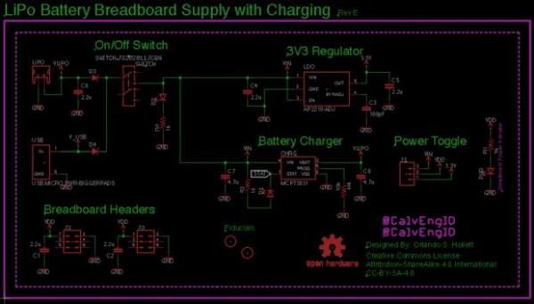
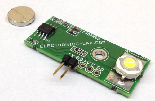
Orlando Hoilett from Calvary Engineering LLC designed a versatile Li-Po battery breadboard power supply and wrote an Instructables on it. This power supply outputs 3.3V to the breadboard and takes input from a single-cell LiPo battery. The breadboard power supply also has the ability to charge the battery without needing to separate it from the circuit board. More importantly, this project is licensed under Open Source Hardware which means anyone can modify, distribute, make, and sell this design.

Key Components
The complete BOM is available at the GitHub repository.
- JST connector
This connector connects directly to the LiPo battery. - 3.3V regulator, AP2210K
3.3V logic is getting increasingly popular among electronics hobbyists and engineers. Also, boosting 3.7V of a LiPo battery to 5V can induce quite a bit of switching noise on the power supply. Linearly converting 3.7V to 3.3V is the best way to avoid this problem. - Battery Charger, MCP73831T
This power supply has a charger built into the board so you can charge the battery without removing it from the power supply. - Voltage Selection Jumper
The voltage selection headers are 3 pin male headers and they are labeled as 3.3V (or VReg) and VRAW (or LiPo). Connect the center pin to 3.3V to get power from the regulator. Connect the center pin to VRAW to get power directly from the LiPo battery. - DPDT Switch
This switch lets you power down the board without removing the battery. - LED indicators
LEDs are used to indicate the current status of the board.
Details
This board breaks out the LiPo battery to the breadboard power rails on both sides. It has a DPDT switch to power down the board. The AP2210K IC has an ENABLE pin which is pulled down to the ground using the DPDT switch in order to enter the low power mode. In low power mode, the regulator and all the LEDs get disabled and draws almost no current from the LiPo. More about the AP2210K regulator IC is on this datasheet.
Read More: VERSATILE AND OPEN SOURCE LIPO BBATTERY BREADBOARD POWER SUPPLY
The post VERSATILE AND OPEN SOURCE LIPO BBATTERY BREADBOARD POWER SUPPLY appeared first on PIC Microcontroller.